
 WhatsApp: +86 16626708626
 Email:
  Phone: +86 16626708626
Description
Key Technical Specifications
| Parameter | Specification |
| Model Part Number | FC-SDO-0824 |
| System Compatibility | Honeywell Safety Manager / Fail Safe Controller (FSC) |
| Number of Output Channels | 8 isolated digital output channels |
| Nominal Output Voltage | 24 V DC (−15% / +30%) |
| Output Current Capacity | 2.0 A per channel (Max 10 A total module current) |
| Safety Certification | SIL3 certified according to IEC 61508 / IEC 61511 |
| Diagnostic Coverage | Short-circuit protection, open-load detection, and automated pulse testing (>99%) |
| Galvanic Isolation | 1500 V RMS field-to-logic isolation |
| Power Dissipation | Max 8.5 W at full rated load |
| Operating Temperature | −5°C to +70°C (Cabinet internal ambient) |
| Physical Dimensions (H x W x D) | 176 × 35.2 × 212 mm (6.93 × 1.39 × 8.35 inches) |
| Unit Weight | 0.85 kg (1.87 lbs) |
Product Introduction & Supply Chain Strategy
The Honeywell FC-SDO-0824 is an 8-channel Safe Digital Output module designed for high-integrity Emergency Shutdown (ESD), Fire & Gas (F&G), and Burner Management Systems (BMS). Executing fail-safe output commands, it directly energizes and de-energizes critical field devices—such as solenoid valves, trip relays, and alarm sirens—while performing continuous diagnostic self-tests to catch short circuits or wire breaks before they cause a failure.
Procuring the FC-SDO-0824 as New Surplus provides a robust risk-mitigation strategy for plant maintenance teams. Refurbished safety I/O modules present significant risks of degraded output switches or weakened line-monitoring circuits, which can lead to spurious plant trips or dangerous fail-to-stop conditions. Sourcing factory-fresh surplus stock ensures original semiconductor performance, guarantees an operational lifespan of 10 to 15 years, and lowers the Total Cost of Ownership (TCO) compared to unplanned process downtime.
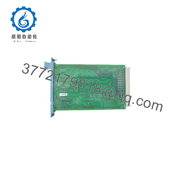
FC-SDO-0824
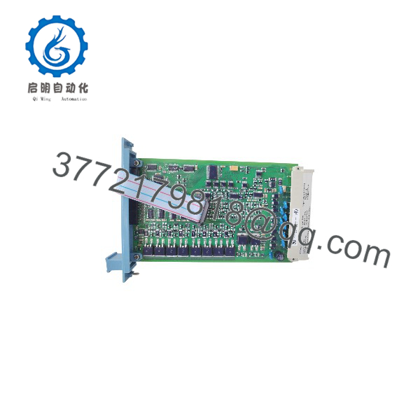
FC-SDO-0824
Installation & Configuration Guide
Stage 1: Pre-Installation (Prep & Safety)
- Execute complete Lock-Out/Tag-Out (LOTO) procedures on the power feeds to the I/O rack.
- Put on an anti-static wrist strap connected to cabinet ground to protect the card’s ESD-sensitive components.
- Record wire color codes, channel mappings, and field load ratings from the module being replaced.
- Check the targeted I/O chassis slot for pin integrity or debris.
Stage 2: Module Removal
- De-energize the field power supply feeding the specific output channel group.
- Unbolt the top and bottom retention fasteners on the front panel of the existing module.
- Extract the card straight out along the chassis guide rails to avoid flexing backplane connections.
Stage 3: Installation & Seating
- Inspect the backplane connectors on the new FC-SDO-0824 unit for straightness and cleanliness.
- Align the module circuit board with the chassis guide slots and slide it smoothly into position.
- Press firmly to seat the backplane pins completely, then tighten the retention screws.
Stage 4: Power-On & Testing
- Re-apply 24 V DC field power and rack power.
- Check the front panel channel status LEDs: Green indicates active output, Off indicates de-energized, and Flashing Red indicates a channel fault (open wire or short circuit).
- Perform a loop test from the Safety Builder console to verify output switching and line-monitoring signals.
Firmware/Software Versions & Upgrade Notes
- System Integration Requirements: The FC-SDO-0824 requires proper hardware configuration within Safety Builder software to define channel load thresholds and line-monitoring parameters.
- Line Monitoring Setup: If channels are wired to low-current loads (less than 50 mA), ensure appropriate end-of-line (EOL) resistors are configured to prevent false “open wire” fault alarms.
- Hot-Swap Compliance: Hot-swapping the FC-SDO-0824 requires verifying site safety protocols. In active SIL3 loops, taking an output module offline can trigger safety trip logic unless channel bypasses are enabled in software.
- Redundant Configuration: When installed in redundant I/O rack pairs, both modules must share identical hardware revisions to maintain synchronized diagnostic voting.
Frequently Asked Questions (FAQ)
Q: How do you verify that this FC- is New Surplus?
All units are retrieved directly from canceled construction projects and OEM surplus reserves. They arrive in factory anti-static packaging, show zero wear on backplane pin contacts or terminal connections, and pass thorough visual and electrical QC testing before dispatch.
Q: Can this module handle inductive loads like large solenoid valves?
Yes. The FC- supplies up to 2.0 A per channel and includes integrated freewheeling protection against inductive kickback. However, installing external suppression diodes across heavy solenoid coils is recommended to extend channel lifespan.
Q: What causes a Channel Fault light on the front panel?
A fault light typically indicates a line-monitoring trip—either a short circuit in the field wiring, an open circuit (wire break), or a missing 24 V DC field power supply connection.
Q: Why buy New Surplus instead of a refurbished module?
Refurbished output cards often suffer from fatigued power MOSFETs and degraded diagnostic optocouplers. In a safety system, a failed output card can trigger a full process shutdown costing tens of thousands of dollars per hour. New Surplus guarantees original manufacturing quality without thermal wear.
Q: What warranty comes with this module?
The FC- comes with a complete 12 month replacement warranty, giving you factory-level peace of mind without OEM manufacturing lead times.



