
 WhatsApp: +86 16626708626
 Email:
  Phone: +86 16626708626
Description
Key Technical Specifications
| Parameter | Specification |
| Model Part Number | FE-USI-0002 |
| System Compatibility | Honeywell Safety Manager / Fail Safe Controller (FSC) |
| Interface Type | Universal Safety Interface (USI) for Safety Network communication |
| Operating Power | 5 V DC and 24 V DC system backplane supply |
| Communication Channels | Multi-channel Tx/Rx serial communication links (Channels A, B, C, D) |
| Safety Integrity Level | SIL3 certified in accordance with IEC 61508 standards |
| Diagnostic Coverage | Continuous link state monitoring with LED indicators |
| Mounting Configuration | Chassis slot mounting in Safety Manager rack |
| Operating Temperature | −5°C to +70°C (Cabinet internal ambient) |
| Relative Humidity | 5% to 95% non-condensing |
| Dimensions (H x W x D) | 176 × 35.2 × 212 mm (6.93 × 1.39 × 8.35 inches) |
| Unit Weight | 0.90 kg (1.98 lbs) |
Product Introduction & Supply Chain Strategy
The Honeywell FE-USI-0002 is a Universal Safety Interface (USI) module designed for the Honeywell Safety Manager architecture. It serves as a vital communications gateway, routing peer-to-peer data and system diagnostic information between distributed safety nodes, control processors, and supervisory DCS networks without compromising safety loop execution.
Stocking the FE-USI-0002 as New Surplus provides critical operational protection for plants running mature Safety Manager installations. Refurbished interface cards frequently suffer from degraded transceiver chips or aged signal isolation transformers, which can cause intermittent communication drops or bus arbitration failures. Acquiring factory-fresh surplus stock preserves original signal integrity, ensures a 10-to-15 year operating lifespan, and minimizes Total Cost of Ownership (TCO) by avoiding emergency plant shutdowns.
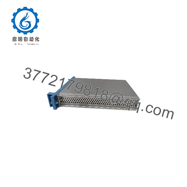
FE-USI-0002
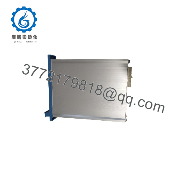
FE-USI-0002
Installation & Configuration Guide
Stage 1: Pre-Installation (Prep & Safety)
- Execute complete Lock-Out/Tag-Out (LOTO) procedures on the power feeds to the controller rack.
- Put on a grounded ESD wrist strap before handling the card to protect sensitive bus transceiver circuits.
- Record communication address DIP switches or jumper settings from the original module.
- Inspect the target backplane slot for connector pin integrity and dust build-up.
Stage 2: Removal
- De-activate the communication node or switch the controller to a safe standby state.
- Unbolt the top and bottom retention screws on the module front panel.
- Pull the module straight out along the chassis guide rails using the front panel handle.
Stage 3: Installation & Seating
- Set the hardware address switches on the new FE-USI-0002 to match the module being replaced.
- Align the module circuit board with the chassis guide slots and slide it smoothly into position.
- Press firmly to seat the card edge connector into the backplane socket, then tighten the retention screws.
Stage 4: Power-On & Testing
- Re-apply system power to the rack.
- Monitor front panel Tx/Rx LEDs for active data polling on communication channels A, B, C, and D.
- Verify node connectivity and communication status in Safety Builder diagnostic software.
Firmware/Software Versions & Upgrade Notes
- System Integration Requirements: Ensure the module’s hardware revision and build parameters align with the running Safety Manager software release (e.g., Safety Builder R120/R130).
- Communication Addressing: Node addressing switches must be set prior to powering up the chassis; address changes are not recognized dynamically during operation.
- Redundant Link Configuration: When installed in redundant communication architectures, verify that both active and standby interface modules share identical hardware revisions to prevent link synchronization faults.
- Cable Integrity: Ensure shielded twisted-pair or fiber interface convertors connected to the module are properly grounded to prevent ground loops from disrupting serial communications.
Frequently Asked Questions (FAQ)
Q: How can you verify that this FE-USI-0002 module is New Surplus?
All units are sourced directly from canceled engineering projects and factory overstock. They arrive in factory ESD packaging, feature un-marred card edge connectors, show zero thermal wear, and pass full functional QC testing prior to dispatch.
Q: What function do the Tx/Rx LEDs on the front panel serve?
The front panel includes separate Tx (Transmit) and Rx (Receive) LED indicators for communication channels A, B, C, and D, providing immediate visual confirmation of active data flow and channel activity.
Q: Why buy New Surplus instead of a refurbished module?
Refurbished communication cards often contain degraded optocouplers and fatigued RS-485/serial drivers that fail under elevated operating temperatures. In a SIL3 safety system, an interface failure can sever communication with the DCS or sister controllers, triggering a false plant trip. New Surplus provides original factory reliability.
Q: Is special software needed when swapping this interface module?
No software installation is required on the module itself, but the node address must match the Safety Builder project topology file to re-establish communication upon power-up.
Q: What warranty coverage applies to this module?
The FE-USI-0002 comes with a complete 12-to-24 month functional replacement warranty, delivering original factory performance without long OEM lead times.



