
 WhatsApp: +86 16626708626
 Email:
  Phone: +86 16626708626
Description
Key Technical Specifications
| Parameter | Value |
|---|---|
| Manufacturer | Honeywell |
| Full Model | FTA-T-02 |
| Product Family | Fail Safe Control hardware / FSC |
| Product Type | Fail-safe digital output field termination assembly |
| Primary Function | Interfaces System Interconnection Cables to field wiring |
| Supported Output Supply Class | 24/48/60 V DC |
| Number of Field Channels | 24 |
| Channel Grouping | 6 groups of 4 channels |
| System Connection | Six System Interconnection Cable connectors |
| SIC Connector Identification | 1A, 1B, 2A, 2B, 3A, 3B |
| Field Connection Type | Screw terminals |
| Maximum Continuous Current | 2 A per channel |
| Maximum Voltage, Overvoltage Category 3 | 36 V AC / 50 V DC |
| Maximum Voltage, Overvoltage Category 2 | 125 V AC / 150 V DC |
| Approvals | CE, UL |
| Mounting | Universal snap-in facility for DIN EN rail |
| Compatible Rail Types | TS32 or TS35 × 7.5 |
| Module Dimensions | 145 × 70 × 57 mm, L × W × H |
| Rail Length Required | 146 mm |
| Terminal-Fuse Requirement | Use only the approved fuse specification shown in the applicable Honeywell FSC wiring documentation |
Honeywell’s Fail Safe Control Hardware Manual identifies FTA-T-02 as a 24-channel fail-safe digital-output Field Termination Assembly for 24/48/60 V DC systems. It provides the interface between six System Interconnection Cables and external field wiring through screw terminals, with channels arranged in six four-channel groups and rated for 2 A continuous current per channel.
Product Introduction
The Honeywell FTA-T-02 is a Fail Safe Control field termination assembly for 24-channel digital-output circuits. It connects FSC system interconnection cables to external field wiring through labeled screw terminals, allowing safety-related output circuits to reach relays, solenoids, valves, alarms, and other approved field devices.
This part is a termination assembly, not the output logic module itself. It does not independently create output commands or replace an FSC controller/output module. Correct replacement requires matching the FTA-T-02, connected SIC cable set, output-module type, field supply voltage, fuse arrangement, terminal wiring, and approved cause-and-effect documentation.
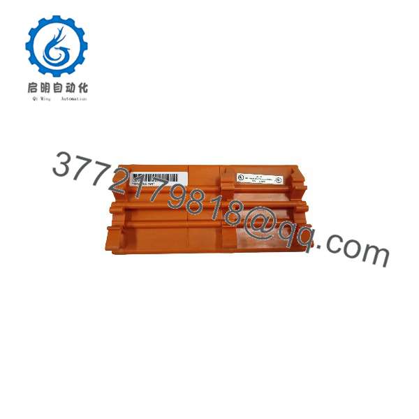
FTA-T-02
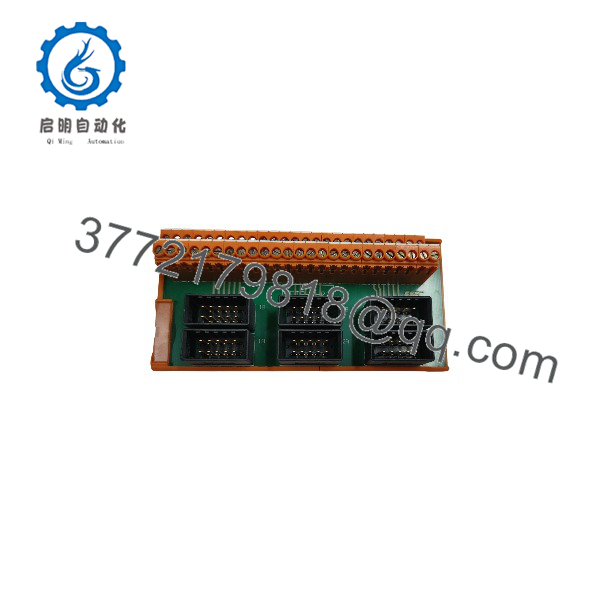
FTA-T-02
Troubleshooting Quick Reference
| Symptom | Possible Cause | Relevance to This Part | Quick Check Method | Recommendation |
|---|---|---|---|---|
| Multiple field outputs are dead | Lost 24/48/60 V DC field supply, open common fuse, disconnected SIC cable, upstream output-module fault | ✅ Medium | Measure the field supply at the applicable FTA-T-02 terminals using the approved drawing; inspect all six SIC connectors and upstream output diagnostics | Check supply, fuses, and cable seating before replacing the FTA |
| One field device does not energize | Loose screw terminal, open wire, blown branch fuse, failed field coil, damaged terminal path, output-module channel fault | ✅ Medium | Measure voltage at the FTA terminal and directly at the field device while commanded ON; check coil resistance and return path | Repair wiring or field device first; replace FTA only if the terminal path is proven open or damaged |
| Output operates at module but not at field terminal | Incorrect terminal identification, broken SIC-to-FTA path, loose connector, damaged FTA track or terminal | ✅ High | Compare output-module status with voltage at the specified FTA terminal; reseat the relevant SIC connector with power isolated; inspect terminal damage | Verify cable and terminal mapping. Replace FTA if the internal path is confirmed defective |
| Fuse repeatedly opens | Shorted valve/relay coil, damaged cable, wrong field voltage, excessive load current, incorrect fuse rating | ❌ Usually low | Lock out power; isolate the load; measure coil resistance and cable insulation; verify the circuit voltage and approved fuse type | Remove the downstream fault before installing a replacement FTA |
| Field device stays energized after command turns OFF | External backfeed, miswired relay contact, shared common, welded relay, incorrect return wiring | ❌ Low | Disconnect the field load under approved procedure; measure voltage at the FTA terminal; trace backfeed from alternate power sources | Correct field wiring or relay problem before condemning the FTA |
| Intermittent output fault during vibration | Loose screw terminal, improper conductor ferrule, damaged SIC connector, rail mounting issue | ✅ Medium | De-energize; verify terminal torque to the approved value; inspect ferrules and conductor strands; check SIC connector latches | Re-terminate damaged wiring and reseat connectors before replacement |
| Replacement FTA does not match existing wiring | Wrong FTA model, different terminal format, different channel mapping, incorrect output voltage family | ✅ High | Compare part number, terminal drawings, SIC labels, field-wire numbers, and group assignments 1A through 3B | Do not move wires by assumption. Use the approved Honeywell termination drawing |
| Safety output test fails after replacement | Channel-to-terminal mismatch, missing fusible link, wrong field polarity, configuration mismatch, incomplete proof test | ✅ High | Compare cause-and-effect chart, loop drawings, terminal numbers, and output module channel mapping; perform approved functional testing | Stop and follow the site safety-management and proof-test procedure |
| Visible heat damage or cracked terminal block | Overcurrent, loose terminal, poor conductor sizing, contamination, incorrect fuse protection | ✅ High | Isolate power; inspect terminals, conductors, labels, and adjacent wiring for discoloration or melted insulation | Replace damaged hardware and determine the electrical root cause before re-energizing |
Field warning: An FTA-T-02 failure is less common than a field wiring, fuse, coil, or upstream output-module fault. Check the output status at the controller/module, then measure at the FTA screw terminal, then at the final device. That three-point check isolates the problem without guessing.
❗ Do not jumper terminals to force a valve, relay, shutdown circuit, or alarm. This assembly is used in fail-safe output circuits. A jumper can bypass the designed safety action, energize the wrong load, damage upstream electronics, and invalidate a required proof test.
If you need help, provide qualified support personnel with the complete label, photographs of all SIC connectors and terminals, channel/group number, wiring drawings, fuse ratings, field supply voltage, output-module diagnostic status, and measured terminal voltages.
Frequently Asked Questions (FAQ)
What is the Honeywell ?
The is a Honeywell fail-safe digital-output Field Termination Assembly. It routes 24 output channels from System Interconnection Cables to external field wiring through screw terminals. It supports 24/48/60 V DC output circuits and divides the 24 channels into six groups of four.
Is an output card or a termination board?
It is a termination board, not the active output card. The upstream Honeywell FSC output electronics generate and supervise the output signal; the provides the physical field-wiring interface and cable termination. If an upstream module reports a channel fault, replacing the FTA may not solve it unless the terminal assembly, SIC connection, or field wiring path is proven defective.
How many channels does support?
It supports 24 channels, arranged as six groups of four channels. Honeywell identifies the six System Interconnection Cable connectors as 1A, 1B, 2A, 2B, 3A, and 3B. Maintain those group and cable identities when documenting or replacing wiring.
What voltage and current can it handle?
The is intended for 24 V DC, 48 V DC, or 60 V DC fail-safe digital-output applications. Honeywell specifies a maximum continuous current of 2 A per channel. The detailed hardware manual also lists voltage limits of 36 V AC / 50 V DC for IEC 1010 overvoltage category 3 and 125 V AC / 150 V DC for category 2.
Can I use as a direct replacement for FTA-E-02?
Not automatically. Both are associated with 24-channel fail-safe digital-output applications, but the termination style differs. The uses screw terminals, while the FTA-E-02 interfaces external wiring through an E-56 ELCO socket. You must match the installed termination format, field cable design, physical mounting, and approved wiring documentation.
Can I hot-swap the ?
Do not hot-swap it unless the specific safety-system maintenance procedure explicitly allows it and the process risk has been assessed. Removing the FTA can interrupt multiple output circuits, trigger trips, de-energize solenoids, or defeat field connections. Follow the site’s management-of-change, bypass authorization, isolation, and post-maintenance proof-test requirements.
Why do I need the SIC connector labels when replacing the module?
The SIC labels identify the system cable and associated output group. Mixing up 1A, 1B, 2A, 2B, 3A, 3B can route an output channel to the wrong field device. That can create incorrect alarms, unexpected equipment trips, or a failed safety-function test. Photograph and label every connector before removal, then verify against the wiring drawing after installation.
What should a supplier inspect before shipping a surplus ?
Ask for the full part-number label, clear terminal and connector photographs, inspection for heat damage, cracked plastic, corrosion, stripped screw terminals, damaged DIN-rail clip, and signs of field rework. A supplier can continuity-check terminal paths and inspect the board, but your site still must perform the approved loop checks and safety proof test after installation.



