WhatsApp: +86 16626708626
 Email:
 Phone: +86 16626708626
Description
Key Technical Specifications
| Parameter | Value |
|---|---|
| Manufacturer | Honeywell |
| Model | MC-PDIY22 |
| Part Number | 80363972-150 |
| Module Type | Digital Input Processor (IOP) |
| Input Channel Count | 32 |
| Nominal Input Voltage | 24 VDC |
| Signal Type | DC digital inputs |
| Hardware Configuration | Conformally coated assembly |
| Control System Family | TPS Process Manager I/O |
| I/O Interface | Compatible system I/O processor and field termination arrangement |
| Installation | Designated I/O processor slot in the applicable system hardware |
| Firmware Revision | Verify against the installed system and replacement unit |
| Operating Temperature | Confirm the applicable OEM hardware specification |
| Dimensions and Weight | Verify against the supplied hardware revision |
| Lifecycle Status | Confirm with Honeywell or an authorized lifecycle information source |
Technical note: The channel count, nominal input voltage, model designation, and coating distinction are supported by Honeywell hardware documentation. Exact environmental limits, electrical thresholds, and mechanical dimensions should be confirmed against the applicable OEM specification before engineering approval.
Product Introduction
The Honeywell MC-PDIY22 (80363972-150) is a 32-channel, 24 VDC digital input processor for Honeywell TPS Process Manager I/O systems. It acquires discrete field signals from devices such as limit switches, relay contacts, and equipment status circuits, allowing the control system to monitor operating states and execute configured control logic.
Its conformally coated assembly distinguishes it from the uncoated MU-PDIY22 variant. For maintenance teams supporting installed Honeywell process control hardware, the MC-PDIY22 can serve as a replacement candidate when the complete part number, field termination assembly (FTA), and system configuration match the existing installation.
Key Features and Advantages
- 32 digital input channels: Consolidates multiple 24 VDC field status signals in one processor.
- 24 VDC input architecture: Intended for compatible DC discrete-input circuits.
- Conformal coating: The MC designation identifies a coated assembly intended for applications where the specified board protection is required.
- Process control integration: Designed for the applicable Honeywell TPS Process Manager I/O architecture.
- Legacy maintenance support: Provides a replacement option to investigate when maintaining existing process control installations.
Quality Inspection and Supply Verification
Before purchasing or installing a replacement MC-PDIY22, request documentation that establishes the unit’s identity, condition, and test status.
- Incoming inspection: Verify the Honeywell model number, part number 80363972-150, labels, and serial information where available. Inspect the board and connectors for corrosion, damaged pins, contamination, and visible rework.
- Functional testing: Request a test report identifying the test equipment, applicable hardware configuration, power-up results, and communication or I/O checks actually performed.
- Electrical checks: Perform only the electrical tests prescribed for this assembly. Do not apply insulation-resistance or hipot testing indiscriminately to populated electronic circuitry.
- Configuration verification: Record available firmware and hardware revision information and document any configurable settings.
- Final packaging: Use ESD-protective packaging and suitable cushioning for transport.
Important: These are recommended verification steps, not a claim that every unit has completed these tests. Confirm the actual test records, warranty terms, and product condition with the supplier before purchase.
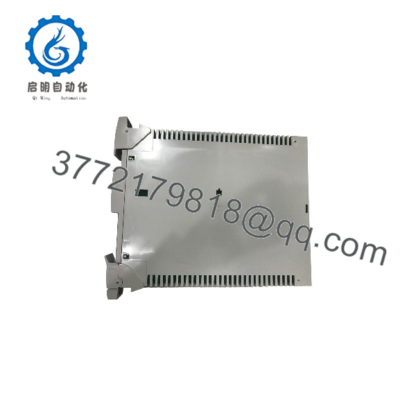
MC-PDIY22
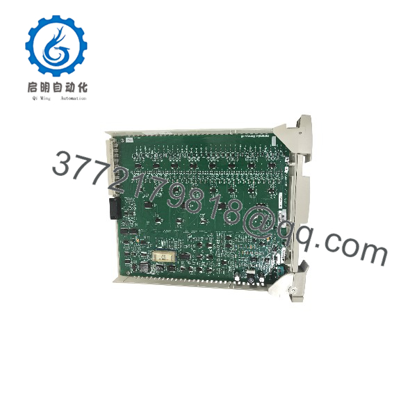
MC-PDIY22
Installation and Configuration Guide
Planning estimate: approximately 30–60 minutes for a straightforward, pre-approved replacement. Actual downtime depends on system access, process isolation, configuration requirements, and commissioning results. Do not assume the work can be completed within 30 minutes.
Stage 1: Pre-Installation Preparation
- Coordinate the outage. Obtain the required maintenance authorization and notify operations. Determine whether the affected input signals participate in interlocks, permissives, alarms, or protective functions.
- Place the process in a safe state. Follow the site’s approved isolation procedure. Apply lockout/tagout where required and verify electrical conditions before handling the equipment.
- Confirm the replacement. Compare the existing card label with the replacement. Check the full model and part number, hardware revision, coating designation, and any applicable system compatibility requirements.
- Document the existing configuration. Photograph the installed module, rack position, FTA connections, cable labels, and relevant system diagnostics.
- Back up the control configuration. Follow the site’s approved procedure for saving controller configuration and relevant I/O assignments. Do not assume the IOP itself contains the application logic.
Tools and documentation: ESD wrist strap and mat, appropriate insulated tools, multimeter, wire labels, camera, applicable Honeywell installation documentation, and authorized engineering workstation access.
Stage 2: Remove the Existing Module
- Verify the equipment is in the approved maintenance state.
- Identify the exact processor slot and associated field termination assembly.
- Record diagnostic indicators and system alarms before removal.
- Disconnect or release the module only as specified by the applicable Honeywell hardware manual.
- Inspect the card guides, connector, rack interface, and accessible termination hardware for damage or contamination.
- Retain the removed module until the replacement has passed commissioning and the original configuration has been verified.
⚠️ Do not assume hot-swap capability. Confirm whether the installed hardware configuration permits powered removal and insertion. If the applicable documentation does not explicitly authorize hot swapping, use the approved de-energized replacement procedure.
Stage 3: Install the Replacement Module
- Verify the complete part number. Confirm MC-PDIY22 and the required 80363972-150 variant, including any hardware or revision restrictions specified for the installation.
- Apply ESD precautions. Keep the replacement in its protective packaging until the installation area is ready.
- Inspect before insertion. Check connector condition, board integrity, and mechanical alignment.
- Install in the designated slot. Follow the OEM procedure for insertion, retention, and connector engagement. Never force the card into the rack.
- Verify field termination compatibility. Confirm the FTA type, wiring arrangement, terminal assignments, and applicable channel mapping against the approved drawings.
- Check all connections. Verify that connectors and retaining mechanisms are correctly secured.
Pre-installation checklist:
Stage 4: Power-Up and Commissioning
- Perform the required pre-power checks. Use the OEM procedure to verify connections and supply conditions. Avoid applying test voltages to signal circuits unless the manual authorizes them.
- Restore power according to the approved sequence. Observe the module indicators and system diagnostics. Interpret LED states using the applicable hardware manual rather than assuming a generic green RUN/red ERR convention.
- Verify system recognition. Confirm that the controller or I/O subsystem recognizes the processor and that no new hardware, communication, or configuration faults appear.
- Check channel mapping. Compare the configured channel assignments with the approved I/O database and field wiring drawings.
- Test representative inputs. With operations authorization, exercise selected field contacts or approved test signals and verify that the correct status appears in the control system.
- Validate all required points. Test the affected channels and associated alarms, permissives, and interlocks according to the approved commissioning procedure.
- Document the results. Record the installed part number, test results, outstanding faults, and maintenance sign-off before returning the equipment to service.
Replacement Pitfalls to Avoid
- Firmware and hardware revisions: A matching model number does not automatically establish compatibility with every installed system release. Confirm the supported revision before installation.
- Incorrect FTA or wiring arrangement: A mechanically compatible card may still be unsuitable for the existing termination and signal configuration.
- Incorrect input voltage or signal type: Verify field circuit voltage and the OEM-defined input thresholds before applying test signals.
- Unverified hot swapping: Removing an IOP under power without explicit authorization can disrupt control functions or damage hardware.
- Incomplete functional testing: A successful power-up does not prove that every field input, alarm, or interlock works correctly.
Frequently Asked Questions
Q1. What does the Honeywell MC- do?
The MC- is a 32-channel, 24 VDC digital input processor used in the Honeywell TPS Process Manager I/O family. It acquires discrete field signals for use by the associated process control system.
Q2. What is the part number for the MC-?
The associated part number is 80363972-150. Verify both the model and complete part number against the installed hardware before ordering. Other revisions or similarly named modules should not be treated as interchangeable without confirmation.
Q3. Is the MC- obsolete?
Its current lifecycle status should be confirmed through Honeywell’s applicable lifecycle documentation or a qualified supplier. Because this is legacy process control hardware, buyers should verify stock availability, traceability, and replacement support rather than assume new factory production continues.
Q4. Is the MC- the same as the MU-?
They are related variants, but they are not identical in board construction. Honeywell’s hardware documentation identifies the MC prefix as the conformally coated version and the MU- as the corresponding uncoated version. Confirm that the coating variant meets the site’s requirements and is approved for the intended installation.
Q5. Can I hot-swap the MC- without shutting down the system?
Do not assume that you can. Hot-swap permission depends on the applicable rack architecture, installation arrangement, and OEM procedure. Confirm the approved replacement method before removing the existing card. If powered replacement is not explicitly supported, schedule an appropriate shutdown or isolation.
Q6. Will replacing the MC- erase the control logic?
The IOP should not automatically be treated as the storage location for the entire controller application. However, the replacement may require hardware recognition, configuration verification, or restoration of applicable settings. Back up the control configuration and document the existing I/O assignments before starting maintenance.
Q7. Can you supply a new original MC- with a warranty?
Availability, condition, and warranty must be confirmed for the specific unit being quoted. Ask the supplier to distinguish among new original, new surplus, and refurbished and tested stock. Request photographs of the actual unit, label and part-number verification, applicable test documentation, lead time, and written warranty terms.
The purchase price alone does not establish authenticity or remaining service life. For a critical control-system spare, prioritize traceability and documented condition.