 WhatsApp: +86 16626708626
 Email:
 Phone: +86 16626708626
Description
Key Technical Specifications
The following table prioritizes Honeywell hardware documentation for model identification and configuration. Electrical load limits and environmental ratings should be checked against the applicable product manual rather than inferred from reseller listings.
| Parameter | Specification |
|---|---|
| Manufacturer | Honeywell |
| Model | MC-TDOD14 |
| Part number | 51309153-175 |
| Product type | Solid-state digital output Field Termination Assembly |
| Output channel count | 16 |
| Output signal range | 3–30 VDC |
| Terminal type | Compression terminals, Terminal Type C |
| Mounting size | Size B |
| Compliance configuration | CE-compliant version |
| Field interface | Digital output field wiring |
| System integration | Compatible Honeywell I/O architecture; verify the specific I/O processor and system generation |
| Board protection | Confirm the coating specification for the actual assembly |
| Maximum current per channel | Verify against the applicable Honeywell manual |
| Maximum aggregate current | Verify against the applicable Honeywell manual |
| Operating temperature | Verify against the applicable Honeywell manual |
| Lifecycle status | Confirm current OEM status |
Sources: Honeywell hardware configuration documentation and model-number tables.
Compatibility warning: The MC-TDOD14 is not interchangeable with every Honeywell digital output FTA. For example, the MC-TDOD13 is also a 16-channel, 3–30 VDC assembly, but its documented part number and compliance configuration differ. Match the full model and part number, terminal type, wiring interface, and host I/O hardware before ordering.
Product Introduction & Supply Chain Strategy
The Honeywell MC-TDOD14 (51309153-175) is a 16-channel solid-state digital output FTA with compression terminals for 3–30 VDC field signals. It provides the termination interface between compatible Honeywell digital output hardware and field devices such as relays, solenoids, and discrete control circuits. Its exact electrical limits depend on the approved system configuration and associated output hardware.
For legacy control installations, maintaining verified replacement inventory can reduce the risk of extended downtime when a termination assembly fails. Evaluate Total Cost of Ownership (TCO), source traceability, and replenishment lead time before setting Min/Max stock levels. Where the assembly supports critical process functions and replacement lead times are uncertain, a one-unit buffer stock may be justified while longer-term compatibility and lifecycle support are assessed.
Installation & Configuration Guide
The MC-TDOD14 is a field termination assembly, not a standalone programmable controller. Its replacement must preserve the correct field wiring and compatibility with the installed Honeywell digital output hardware.
Stage 1: Pre-Installation — Preparation and Safety
- Verify the part number: Confirm MC-TDOD14 and 51309153-175 against the installed assembly and approved parts list.
- Apply lockout/tagout (LOTO): Follow plant electrical isolation procedures and place affected equipment in a safe state.
- Document field wiring: Photograph terminal assignments, polarity, wire labels, and any associated interface connections.
- Verify compatibility: Check the output I/O processor, system generation, terminal configuration, and applicable installation documentation.
- Prepare ESD protection: Use a grounded wrist strap and appropriate antistatic handling materials.
Stage 2: Removal
- Confirm that the affected outputs and connected field devices are in an approved maintenance state.
- Isolate the relevant power sources according to the system manufacturer’s instructions.
- Label each conductor before disconnecting it.
- Release the assembly’s retaining hardware and remove it without forcing connectors or terminals.
- Inspect the mounting position, connectors, and wiring for damage, loose contacts, or contamination.
Stage 3: Installation — Wiring and Seating
- Compare the replacement’s model, part number, terminal arrangement, and hardware revision with the original.
- Mount the assembly in the designated position using the approved hardware.
- Reconnect the field conductors according to the original wiring drawings.
- Verify output polarity, load voltage, wire identification, and terminal tightness.
- Confirm that the associated I/O processor and interface cables match the approved configuration.
Stage 4: Power-On and Functional Testing
- Inspect the field supply and output circuits before restoring power.
- Reenergize the system using the approved startup sequence.
- Check controller diagnostics and I/O status indications.
- Test each required output channel using an approved commissioning procedure.
- Verify the actual response of connected field devices and confirm that interlocks and permissives remain functional.
- Record the replacement part number, test results, and any diagnostic messages before returning the equipment to service.
Important: Do not assume that the MC-TDOD14 supports hot swapping. Confirm the approved maintenance procedure before disconnecting the assembly. Do not apply voltage or load-current limits based solely on a reseller listing.
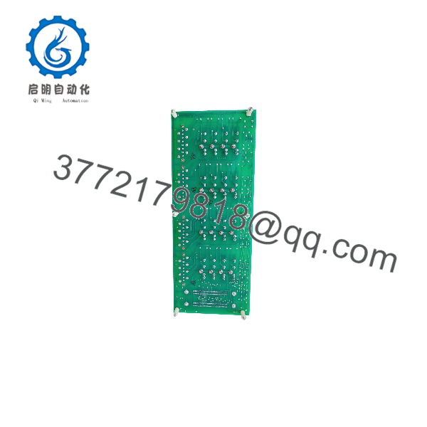
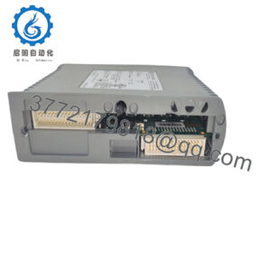
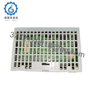
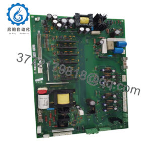
MC-TDOD14 51309153-175
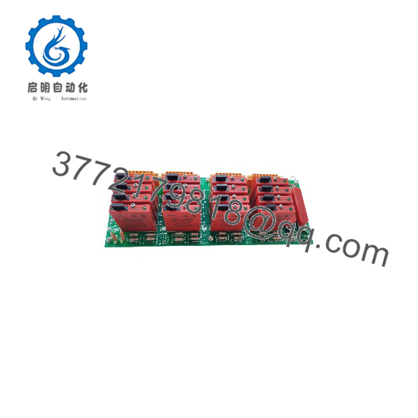
MC-TDOD14 51309153-175
Firmware/Software Versions & Upgrade Notes
The MC- is a field termination assembly rather than an independently programmable controller. Its integration depends on the compatible Honeywell I/O processor, field wiring, and system configuration. The available hardware references do not establish a firmware version specific to this FTA.
- Firmware requirements: Verify the applicable firmware requirements for the associated I/O processor and host control system.
- Hardware compatibility: Confirm the exact FTA part number, terminal configuration, interface cable, and supported output hardware.
- Configuration backup: Record channel assignments, output logic, field supply arrangements, and interlock dependencies before replacement.
- Electrical compatibility: The documented 3–30 VDC output range does not establish the permissible current for every channel or the total assembly. Confirm both limits in the applicable manual.
- Upgrade precautions: Do not upgrade controller firmware solely because the FTA has been replaced. Make software changes only when required by an approved compatibility procedure.
- Commissioning: Verify each affected output and connected field device before releasing the system for normal operation.
For procurement, request the applicable Honeywell installation documentation and confirmation that the offered assembly matches part number 51309153-175.
Frequently Asked Questions (FAQ)
Q1. What is the Honeywell MC- used for?
The MC- is a 16-channel solid-state digital output Field Termination Assembly. It provides compression-terminal connections for compatible Honeywell digital output hardware and 3–30 VDC field circuits.
Q2. Is MC- 51309153-175 the CE-compliant version?
Yes. Honeywell hardware configuration documentation identifies 51309153-175 as the CE-compliant part number for the MC-, with compression terminals and Size B mounting.
Q3. Can the MC- be replaced with an MC-TDOD13?
Do not assume direct interchangeability. Both models are listed as 16-channel, 3–30 VDC digital output FTAs, but the documented part numbers and compliance configurations differ. Verify the wiring, terminal arrangement, associated I/O processor, and approved system configuration before substituting either assembly.
Q4. Is the MC- available as new-original or new-surplus inventory?
Availability and condition depend on the supplier’s actual stock. Request photographs of the physical unit, its identification label, confirmation of part number 51309153-175, and written condition and warranty terms.
For critical applications, ask for inspection records and serial-number traceability where available. A catalog description alone does not establish authenticity or condition.
Q5. Is the MC- discontinued?
Its current official OEM lifecycle status has not been conclusively verified. Confirm availability, support status, and any recommended replacement with Honeywell or an authorized support channel before committing to a last-time-buy strategy.
Q6. Can I replace the MC- while the system is running?
Do not assume live replacement is permitted. The answer depends on the installed system architecture and the manufacturer’s maintenance procedure. Isolate the equipment as required, assess the impact on connected field devices, and verify all affected outputs before returning the system to service.
Q7. What warranty should I expect when purchasing the MC-?
Warranty terms depend on the supplier. Obtain written confirmation of the warranty duration, coverage exclusions, return authorization procedure, and remedies for verified defects. Also confirm that the supplied unit matches the required part number and condition.