 WhatsApp: +86 16626708626
 Email:
 Phone: +86 16626708626
Description
Key Technical Specifications
| Parameter | Specification |
|---|---|
| Manufacturer | Honeywell |
| Model | MN7234A2008 |
| Product category | HVAC damper and valve actuator |
| Actuator type | Direct-coupled rotary |
| Return mechanism | Non-spring return |
| Rated torque | 300 lb-in (34 Nm) |
| Supply voltage | 24 V AC/DC |
| AC frequency | 50/60 Hz |
| Power consumption | 8 VA driving; approximately 6 W |
| Modulating control | 0–10 V DC or 2–10 V DC |
| Current control | 4–20 mA with a 500 Ω shunt resistor |
| Position feedback | 0–10 V DC or 2–10 V DC, depending on configuration |
| Rotation angle | Approximately 95° |
| Nominal running time | Approximately 95 seconds at 60 Hz, subject to load and operating conditions |
| Input impedance | 100 kΩ for voltage input; 500 Ω for current input |
| Manual adjustment | Declutch mechanism |
| Shaft compatibility | Round shafts approximately 3/8–1-1/16 in; square-shaft compatibility depends on adapter |
| Enclosure rating | NEMA 2; IP54 commonly listed |
| Operating temperature | −5 to +140°F (−20 to +60°C) |
| Applications | HVAC dampers, ventilation flaps, louvers, compatible rotary valves |
| Lifecycle status | Discontinued |
Sources: Honeywell actuator product documentation and technical listings. Confirm the exact wiring diagram, control-signal selection, shaft adapter, and feedback configuration against the manual for the supplied unit.
Product Introduction
The Honeywell MN7234A2008 is a 300 lb-in direct-coupled rotary actuator for modulating HVAC dampers and compatible valves. It operates on 24 V AC/DC power and accepts voltage or current control signals. Its non-spring-return design holds position through its drive mechanism rather than automatically returning to a spring-defined safe position after power loss.
The actuator provides adjustable mechanical stroke limits, selectable rotation direction, a manual declutch mechanism, and position feedback. Its 34 Nm torque rating makes it suitable for larger dampers and rotary control elements when the required operating torque falls within the actuator’s limits.
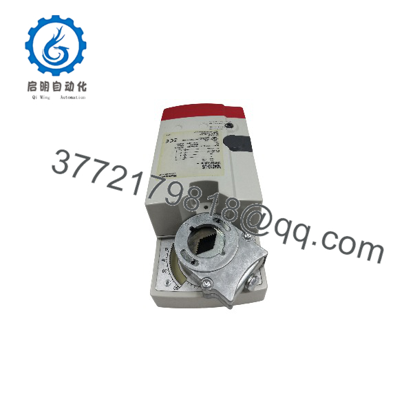
MN7234A2008
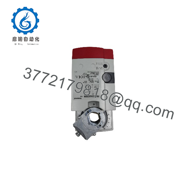
MN7234A2008
Installation & Configuration Guide
Planning estimate: 30–60 minutes for a like-for-like replacement, excluding access work, control-system changes, and functional acceptance testing.
Stage 1: Pre-Installation Preparation
- Confirm the replacement model. Check the nameplate for MN7234A2008 and verify the mounting arrangement, shaft dimensions, and electrical connections.
- Notify building operations. Confirm the HVAC equipment’s operating state and the effect of damper movement on ventilation, pressure control, and safety functions.
- Isolate the electrical supply. Follow site lockout/tagout procedures before disconnecting wiring.
- Prepare the tools. Have a screwdriver, multimeter, wire labels, suitable mounting tools, and a camera available.
- Document the original setup. Photograph the terminal connections, rotation direction, control mode, mechanical stops, shaft position, and feedback wiring.
- Check actuator sizing. Confirm that the damper or valve’s required torque does not exceed the actuator’s rated capability under actual operating conditions.
Stage 2: Remove the Existing Actuator
- Verify that the actuator and connected equipment are safe to work on.
- Label the power, control input, position feedback, and any auxiliary wiring.
- Disconnect the wiring without damaging terminal blocks or cable insulation.
- Support the actuator and release the shaft coupling and anti-rotation bracket.
- Remove the actuator from the shaft and inspect the shaft, linkage, and mounting hardware.
- Check that the damper or valve moves freely through its intended travel. Binding or excessive friction can cause poor positioning or premature actuator failure.
Stage 3: Install the Replacement
- Verify the shaft adapter. Confirm that the adapter matches the shaft’s shape and diameter.
- Set the damper or valve to the required reference position before coupling the actuator.
- Mount the actuator securely and install the anti-rotation bracket.
- Engage the shaft adapter without forcing the shaft or loading the actuator housing.
- Set the mechanical stroke limits within the equipment’s permitted travel.
- Reconnect the wiring according to the model-specific terminal diagram.
- Verify the 24 V AC/DC supply and the selected input mode before energizing.
Critical control-signal note: The actuator can accept 4–20 mA control through the specified 500 Ω shunt resistor across the input. Do not apply a current signal directly without confirming the correct wiring arrangement.
Stage 4: Power-On and Functional Testing
- Check supply voltage and polarity where applicable.
- Restore power according to the approved procedure.
- Apply a known control command, such as the minimum and maximum configured voltage values.
- Confirm that the actuator moves in the intended direction and reaches the correct end positions.
- Verify position feedback against the actual mechanical position.
- Check that the actuator does not stall, bind, or drive the damper beyond its permitted travel.
- Confirm the building automation system receives the correct feedback and responds as intended.
- Document the final settings and obtain the required operations sign-off.
Common replacement risks
- Incorrect rotation direction: The actuator may drive a damper closed when the controller expects it to open.
- Incorrect control input: A 0–10 V, 2–10 V, or 4–20 mA configuration mismatch can cause incorrect positioning.
- Improper shaft coupling: A loose adapter can cause position errors or mechanical slippage.
- Insufficient torque: High damper friction or excessive differential pressure may prevent full travel.
- No spring return: The actuator does not provide automatic spring-driven fail-safe positioning. Confirm that this behavior meets the application’s requirements.
Frequently Asked Questions
Q1. What is the Honeywell MN7234A2008 used for?
It provides modulating rotary control for HVAC dampers, ventilation flaps, louvers, and compatible rotary valves. The actuator converts an electrical control command into mechanical rotation, with a rated torque of 300 lb-in (34 Nm).
Q2. Is the MN7234A2008 a 24 V AC or 24 V DC actuator?
It supports both 24 V AC and 24 V DC operation within the manufacturer’s specified voltage limits. Verify the supply type and wiring diagram before installation.
Q3. Does the actuator support a 4–20 mA control signal?
Yes. The published specifications identify 4–20 mA control with a 500 Ω shunt resistor across the input. Check the model-specific wiring instructions and control-mode selection before connecting the current loop.
Q4. Is the MN7234A2008 discontinued?
Honeywell’s product page identifies the MNxx20/MNxx34 product family as discontinued. Availability may therefore depend on remaining inventory, surplus stock, or aftermarket suppliers. Confirm current lifecycle information with Honeywell if ongoing OEM support is required.
Q5. Can I replace it with another 300 lb-in actuator?
Not based on torque alone. Verify supply voltage, control input, feedback output, rotation angle, shaft dimensions, mounting hardware, enclosure rating, and fail-safe requirements. A substitute with different electrical or mechanical characteristics may require changes to the controller configuration or mounting assembly.
Q6. What happens if power fails?
The is a non-spring-return actuator. It does not use a return spring to drive the damper automatically to a predetermined position after loss of power. If the application requires a defined fail-safe position, select an actuator specifically designed to provide that function.
Q7. How can I confirm the condition of a replacement unit?
Request actual product and nameplate photographs, written confirmation of condition, and the supplier’s test procedure. Distinguish between new original, new surplus, and refurbished units. For a discontinued actuator, also confirm the warranty, physical stock status, dispatch lead time, and return policy before placing the order.
Procurement note: The is a legacy Honeywell actuator. Prioritize exact model verification and electrical/mechanical compatibility over nominal torque matching when sourcing a replacement.