
 WhatsApp: +86 16626708626
 Email:
 Phone: +86 16626708626
Description
Core Product Summary (Brand / Model / Key Attributes)
The Honeywell XF823A is a 12-channel binary input expansion module belonging to the Honeywell Panel-Bus I/O system family. Engineered for building automation, HVAC control, and facility management systems, it expands the input capacity of compatible Honeywell controllers such as the Excel 800 (XL800) and CIPer 50 automation platforms.
Operating on a 24 VAC power supply (50/60 Hz), the module processes up to 12 discrete binary inputs from voltage-free contacts, optical sensors, limit switches, and status relays. It features push-in wiring terminals to simplify field installation, removable terminal blocks for fast module swap-out without rewiring, and front-panel status LEDs for diagnostic monitoring. Communication with the host plant controller occurs over the dedicated Honeywell Panel-Bus interface.
Key Technical Specifications
| Specification Parameter | Technical Detail |
| Product Model | XF823A |
| Product Type | Binary / Digital Input Expansion Module |
| System Family | Honeywell Panel-Bus I/O (Excel 800 / CIPer Series) |
| Number of Inputs | 12 channels |
| Input Type | Binary / Digital (voltage-free dry contacts) |
| Supply Voltage | 24 VAC (±20%), 50/60 Hz |
| Power Consumption | Approx. 5 VA |
| Communication Interface | Honeywell Panel-Bus |
| Terminal Type | Pluggable push-in wire terminals |
| Status Indication | Front-panel LEDs for channel and power status |
| Mounting | Standard 35 mm DIN rail or panel mounting |
| Operating Temperature | 0°C to 50°C (32°F to 122°F) |
Detailed Product Overview
The Honeywell XF823A operates as a distributed I/O slice within building management systems (BMS), providing reliable status monitoring for mechanical and electrical equipment. It converts 12 discrete binary signal states—such as fan proof-of-flow switches, pump status contacts, damper end-switches, and alarm relays—into digital register data for transmission to a central Honeywell controller.
The module connects to the primary controller via the Honeywell Panel-Bus protocol, reducing total wiring run lengths by allowing localized placement inside distributed electrical panels. Field wiring attaches directly to push-in terminal blocks, which lock wires securely while accommodating solid or ferruled conductors. The plug-and-play mechanical housing snaps onto standard 35 mm DIN rails, allowing maintenance technicians to unclip and replace the electronics module without disturbing field terminal connections.
Diagnostic LEDs on the front panel provide real-time status updates for power supply health, communication activity, and individual binary input states, streamlining system commissioning and routine facility maintenance.
Engineering Selection Highlights
- 12 Discrete Binary Channels: Expands control system capacity by accepting up to 12 dry-contact digital inputs within a compact footprint.
- Honeywell Panel-Bus Interface: Connects directly to Excel 800 and CIPer controllers over the Panel-Bus protocol.
- Push-In Terminal Blocks: State-of-the-art push-in connections accelerate field wiring while ensuring vibration-proof contact security.
- Pluggable Module Design: Electronics slice unplugs from its base without disconnecting field signal wiring, minimizing maintenance downtime.
- 24 VAC Power Supply: Operates on standard 24 VAC control panel power (50/60 Hz) consuming approximately 5 VA.
- Visual Diagnostics: Front-face LED indicators offer immediate channel-by-channel status verification during field troubleshooting.
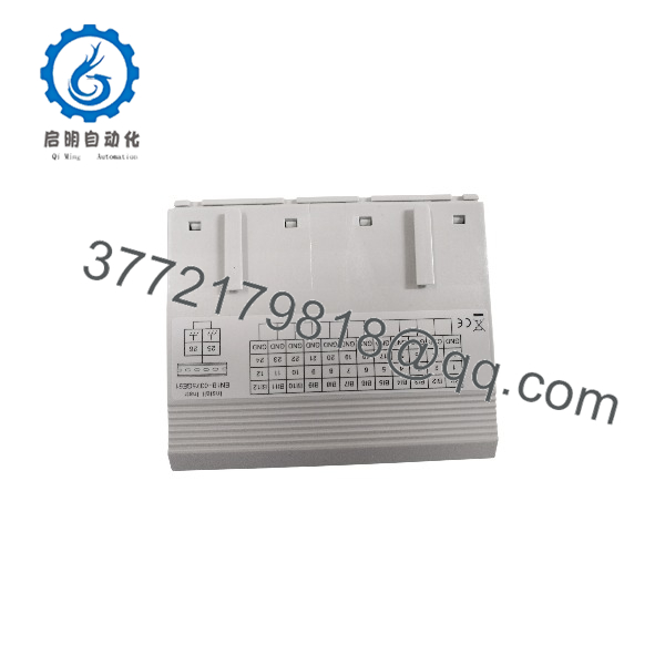
XF823A
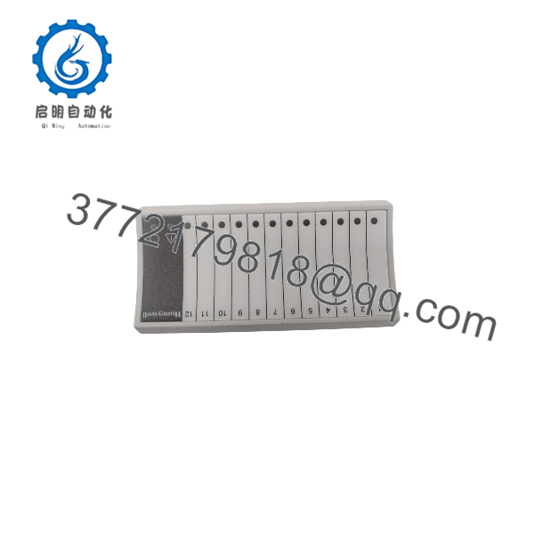
XF823A
System Compatibility & Integration Requirements
| Item / Dependency | Verified Compatibility or Requirement | Practical Note |
| Host Controllers | Honeywell Excel 800 (XL800), CIPer 50 Series | Interconnects via the Panel-Bus interface port. |
| Bus Protocol | Honeywell Panel-Bus | Transmits binary data to host controller over Panel-Bus topology. |
| Power Requirements | 24 VAC (50/60 Hz) Class 2 Transformer | Requires clean 24 VAC power supply (approx. 5 VA consumption). |
| Terminal Connections | Integrated push-in terminal blocks | Accepts solid or ferruled wire sizes up to 1.5 mm² (16 AWG). |
| Software Tooling | Honeywell CARE / CIPer Engineering Tool | Configured via host controller project software. |
Dimensions, Mounting & Connection Notes
- Mounting Method: Mounts on standard 35 mm DIN rail or direct wall/panel surfaces within control enclosures.
- Wiring Setup: Features push-in spring terminals; strip wires to specified length before insertion without needing screwdriver adjustment.
- Operating Bounds: Rated for standard indoor control cabinet environments between 0°C and 50°C with non-condensing relative humidity.
- Housing Rating: Designed for IP20 enclosure rating when installed inside a protective electrical cabinet.
FAQ
What is the Honeywell XF823A?
The Honeywell XF823A is a 12-channel binary digital input module designed to expand input capacity on Honeywell Panel-Bus automation controllers.
Which controllers are compatible with the XF823A?
It integrates with Honeywell Excel 800 (XL800) and CIPer series controllers operating on the Honeywell Panel-Bus network.
What signal types does the XF823A accept?
The module accepts up to 12 binary (digital) inputs from dry, voltage-free contacts such as switches, relays, and status monitors.
What power supply does the XF823A require?
The module operates on a standard 24 VAC supply at 50/60 Hz with a power consumption of approximately 5 VA.
Does replacing an XF823A require rewiring?
No, the module uses pluggable terminal blocks, allowing the electronic module slice to be replaced while leaving the field wiring intact.
How is the XF823A mounted?
It snaps onto a standard 35 mm DIN rail inside an electrical enclosure or control panel.
Verification & Troubleshooting Notes
- Power & Bus Diagnostics: Inspect front-panel power and bus communication LEDs upon power-up to confirm Panel-Bus connectivity with the host controller.
- Input Contact Verification: Measure continuity or voltage across input terminals to confirm field contacts switch properly between open and closed states.
- Terminal Seating Check: Ensure the pluggable terminal blocks are firmly seated into the module body to prevent loose connection errors across the 12 binary channels.



