
 WhatsApp: +86 16626708626
 Email:
 Phone: +86 16626708626
Description
Key Technical Specifications
⚠️ Verification notice: Public OEM documentation for the exact P153DL002 suffix is limited. Third-party listings disagree on whether this specific number is configured as a digital input or digital output module, so the table below reflects commonly listed legacy ICS Triplex TMR I/O characteristics and must be confirmed against the module nameplate, system drawing, and ICS Triplex/Triconex configuration before ordering.
| Parameter | Value |
|---|---|
| Catalog number | P153DL002 |
| Alternate part format | P153/DL/002 |
| Brand | ICS Triplex |
| Product family | Legacy ICS Triplex TMR safety/control system |
| Product type | TMR I/O module |
| Redundancy architecture | Triple Modular Redundancy (TMR) with independent channel processing and voting |
| Reported channel count | 16 channels, configuration-dependent |
| Reported field signal type | 24 V DC discrete signal interface |
| Reported isolation | Galvanic/optical isolation between field and logic sides |
| Diagnostics | Channel health, field-wiring fault detection, backplane communication diagnostics |
| Chassis interface | Keyed ICS Triplex TMR backplane |
| Front indication | Channel/status and module-health LEDs |
| Reported operating temperature | 0 to 60°C for typical TMR cabinet environments; some listings state −20 to +70°C |
| Reported storage temperature | −40 to +85°C |
| Reported humidity | 5 to 95% RH, non-condensing |
| Reported module power | Approximately 3.8 W maximum |
| Safety context | Used in ESD, fire-and-gas, burner management, turbine protection, and critical interlock applications |
| Certification note | Confirm the certification status of the exact hardware revision; do not assume SIL rating from the base model number |
ICS Triplex Trusted TMR systems use three parallel processing paths and majority voting to tolerate a single fault without interrupting the safety function. This architecture is why replacement modules must match the installed chassis, firmware, configuration, and safety-validation basis.
Product Introduction
The ICS Triplex P153DL002, also written P153/DL/002, is a legacy I/O module associated with ICS Triplex triple-modular-redundant safety and critical-control systems. It is used to maintain the field-signal interface in ESD, fire-and-gas, turbine protection, burner management, and other high-integrity applications.
The module is selected for like-for-like repair of an installed ICS Triplex system. Because public OEM data for this exact suffix is sparse and third-party listings conflict on its input/output configuration, procurement should verify the nameplate, revision, terminal layout, and installed system configuration before purchase.
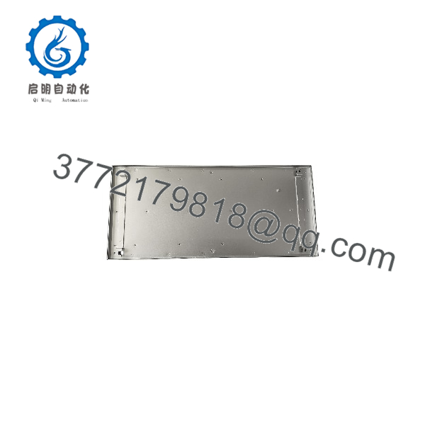
P153DL002
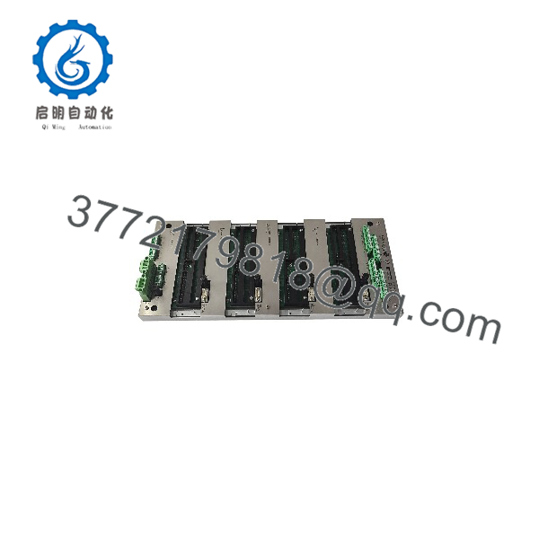
P153DL002
Installation & Configuration Guide
Stage 1: Pre-Installation Preparation
Estimated time: 30–45 minutes.
- ⚠️ Obtain management approval for work on the safety instrumented system and follow the site’s Management of Change (MOC) and safety-validation procedure.
- Place the affected safety function in a controlled safe state; do not bypass protection without formal authorization.
- Apply lockout/tagout to the ICS Triplex chassis field-power and system-power circuits as required by the site procedure.
- Wait at least 5 minutes for internal capacitors and power supplies to discharge.
- Prepare an ESD wrist strap, ESD mat, torque screwdriver, multimeter, wire labels, camera, and the system configuration records.
- Export and archive the controller project, I/O configuration, diagnostic history, and event/SOE records.
- Photograph the module faceplate, revision marking, terminal assignments, field wiring, and chassis slot location.
⚠️ Do not rely on the base number P153DL002 alone. Confirm the full suffix, hardware revision, channel direction, voltage class, and terminal block type.
Stage 2: Removing the Old Module
Estimated time: 15–30 minutes.
- Verify system status and confirm that the module is not actively required for a safety function.
- De-energize the relevant field-power circuit and verify 0 V with a multimeter.
- Label every field wire at the terminal block.
- Disconnect field wiring and remove the terminal block or field cable assembly as applicable.
- Release the module retaining screws or locking mechanism.
- Withdraw the module straight from the chassis to avoid bending backplane pins.
- Inspect the chassis connector, guide rails, terminal block, and replacement module for damage or contamination.
⚠️ Keep the removed P153DL002 available until the replacement has passed channel-level diagnostics and the safety validation is complete.
Stage 3: Installing the New Module
Estimated time: 15–30 minutes.
- Put on a grounded ESD wrist strap and work on an ESD-safe surface.
- Verify the replacement is exactly ICS Triplex P153DL002 / P153/DL/002, with matching hardware revision and terminal configuration.
- Confirm the target chassis slot is compatible and empty.
- Insert the module straight into the keyed backplane connector until it seats fully.
- Secure the retaining screws or locking mechanism to the specified torque.
- Reinstall the terminal block and reconnect labeled field wiring.
- Verify shielding, field-common references, and cable segregation from power wiring.
Self-checklist:
- Exact P153DL002 suffix and revision confirmed
- Input/output direction confirmed against system drawing
- Module fully seated and secured
- Field wiring labels match terminals
- Shielding and grounding restored
- Configuration project available for download
Stage 4: Power-On & Testing
Estimated time: 1–2 hours, depending on safety-validation scope.
- ⚠️ Before restoring field power, check wiring for shorts, incorrect voltage application, and terminal tightness.
- Restore chassis/system power according to the site startup procedure.
- Observe module power, OK/Active, fault, and communication LEDs.
- Download or restore the validated controller project and I/O configuration.
- Confirm that the TMR processor recognizes the module and reports no configuration mismatch.
- Exercise each field point using a controlled, documented test method.
- Verify channel diagnostics, fault reporting, voting behavior, and alarm/SOE capture.
- Complete the site’s post-maintenance proof-test and return the safety function to normal service only after documented approval.
⚠️ If the TMR processor reports a channel mismatch or configuration fault, stop and compare the module revision, channel direction, firmware compatibility, and I/O database before further troubleshooting.
Frequently Asked Questions (FAQ)
Can I hot-swap the ICS Triplex P153DL002?
Do not assume it is hot-swappable. Some ICS Triplex/Triconex platforms support online module replacement, but the correct answer depends on the exact chassis, system version, module type, and site safety procedure. For a legacy safety I/O module, treat replacement as a planned, controlled maintenance activity unless the system documentation explicitly permits online replacement.
Is P153DL002 a digital input or digital output module?
This must be verified. Public third-party listings conflict: one identifies it as a 16-channel digital input module, while another describes a 16-channel 24 V DC sourcing digital output module. Check the module faceplate, terminal designation, wiring drawing, and controller I/O database before ordering.
Is the P153DL002 obsolete?
Yes, it is legacy ICS Triplex hardware. It is no longer a standard current-catalog item, so availability is generally limited to surplus, refurbished, or exchange inventory.
What is the direct replacement?
The direct replacement is another P153DL002 with the same hardware revision, terminal layout, and firmware/configuration compatibility. There is no verified universal modern substitute; migration to a current safety platform is a system-engineering project, not a module swap.
Will replacing the module erase the safety program?
No. The safety application and configuration reside in the TMR processor/controller, not the I/O module. Still, export and archive the project and diagnostic records before removal.
Can I use this module outside a safety application?
Only if the system design, safety case, and site procedure permit it. These modules are intended for high-integrity TMR applications; using an unverified module in a SIL-rated loop can invalidate the safety validation.
Why should I request test evidence?
For legacy TMR modules, condition and revision matter as much as the catalog number. Request photographs of the nameplate, confirmation of firmware/configuration compatibility, functional test records, and a stated warranty period before installation.



