WhatsApp: +86 16626708626
 Email:
 Phone: +86 16626708626
Description
Core Product Summary (Brand / Model / Key Attributes)
The ICS Triplex T8311 is the dedicated TMR Expander Interface Module for the Rockwell Automation ICS Triplex Trusted safety and critical control system. Installed within a Trusted expander chassis (such as the T8300 series), the T8311 serves as the high-speed communication link that connects remote or local I/O expansion racks back to the main T8100 controller chassis. Built around a Hardware Implemented Fault Tolerant (HIFT) Triple Modular Redundant (TMR) architecture with 3-2-0 degraded mode capability, the module maintains determinism and data integrity across expanded system topologies without single points of failure.
Engineered for IEC 61508 SIL 3 safety environments, the T8311 manages inter-chassis bus communication at rates up to 250 Mbps. The module features three isolated Fault Containment Regions (FCR A, B, and C) operating in lock-step to ensure voter consensus and real-time fault isolation. Powered by dual-redundant 20 VDC to 32 VDC supply feeds from the chassis backplane, the T8311 supports online hot-swapping and hot-standby configurations, allowing continuous inter-rack communication during live module maintenance.
Key Technical Specifications
| Parameter | Specification |
| Manufacturer & Series | ICS Triplex / Rockwell Automation Trusted System |
| Model Number | T8311 |
| Module Type | Trusted TMR Expander Interface Module |
| System Architecture | Triple Modular Redundant (TMR) / Hardware Implemented Fault Tolerant (HIFT) |
| Safety Integrity Level | TÜV Certified for IEC 61508 SIL 3 applications |
| Internal Fault Containment | 3 Fault Containment Regions (FCR A, B, and C) |
| Module Clock Speed | 50 MHz |
| Expander Bus Data Rate | 250 Mbps |
| Operating Voltage | 20 VDC to 32 VDC (Dual-redundant 24 VDC nominal feeds) |
| Power Consumption / Heat | 40 W maximum load |
| Operating Temperature | -5 °C to 60 °C (23 °F to 140 °F) |
| Non-Operating Temperature | -25 °C to 70 °C (-13 °F to 158 °F) |
| Relative Humidity | 5% to 95%, non-condensing |
| Dimensions (H × W × D) | 266 mm × 31 mm × 303 mm (10.5 in × 1.2 in × 11.9 in) |
| Module Weight | 1.14 kg (2.51 lb) |
Detailed Product Overview
The ICS Triplex T8311 TMR Expander Interface Module establishes high-integrity data interconnectivity across multi-chassis deployments in the Rockwell Automation Trusted control platform. In large-scale Emergency Shutdown (ESD), Fire and Gas (F&G), Burner Management Systems (BMS), and turbomachinery control applications where input/output points exceed the capacity of a single main chassis, the T8311 links expansion I/O racks directly to the primary T8110-series main processor controllers.
At the hardware level, the T8311 replicates the fault-tolerant design principles of the primary system processor. The module is divided into three physically and galvanically isolated processing paths—Fault Containment Regions A, B, and C. Each region derives its operating voltages independently from the backplane’s dual-redundant 24 VDC power rails and processes inter-chassis communications in lock-step. Hardware-driven voting mechanisms evaluate data transfers continuously, enabling 3-2-0 degraded mode operation that isolates localized signal corruption or component faults without interrupting active process loops or triggering false system alarms.
The T8311 handles data exchanges across the inter-chassis expander bus at speeds up to 250 Mbps. This high throughput ensures that input states from remote T84xx I/O modules and output commands from the main processors remain tightly synchronized within the controller’s logic execution cycles. Integrated front-panel diagnostic LEDs continuously display the operational health of each processing slice and ejector status, simplifying maintenance routines and quickening fault isolation in the field.
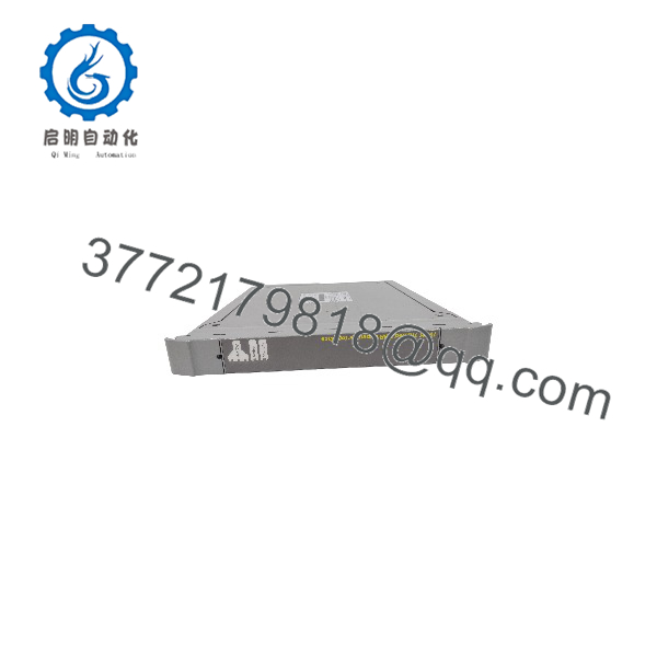
T8311
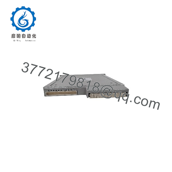
T8311
Engineering Selection Highlights
- High-Speed Inter-Rack Bus: Delivers 250 Mbps expander bus communication to keep distributed I/O data synchronized with the main processor.
- HIFT 3-2-0 Fault Tolerance: Three hardware-isolated channels (FCR A, B, C) ensure continuous data routing even if one internal slice experiences a fault.
- Galvanic Backplane Isolation: Prevents noise propagation between expansion racks and primary processing chassis.
- Hot-Swap Maintenance: Supports live insertion and removal in both active and hot-standby configurations without disrupting running control loops.
- Zero Module-Level Configuration: Hardware configuration is handled automatically via the System Toolset I/O Connection Table without requiring onboard jumper settings.
- SIL 3 Functional Safety: Fully TÜV certified for deployment in safety-critical instrumented loops up to IEC 61508 SIL 3.
System Compatibility & Integration Requirements
| Item / Dependency | Verified Compatibility or Requirement | Practical Note |
| Expansion Chassis | Trusted T8300 Series Chassis | Installs directly into dedicated expander interface slots of the expansion chassis. |
| Primary Controller | Trusted T8100 Controller Chassis | Interfaces back to the primary controller system via inter-chassis expander cabling. |
| Companion Slot / Cable | Module Polarization / Keying Strips | Requires removal of keying pins 1, 2, and 6 on the module connector for proper slot keying. |
| Engineering Toolset | Trusted System Toolset | Software setup requires an entry in the I/O Connection Table specifying chassis and slot numbers. |
| I/O Modules | Trusted T84xx Series Modules | Manages data routing between local expansion rack I/O cards and the main TMR processor. |
Dimensions, Mounting & Connection Notes
- Physical Dimensions: Height 266 mm (10.5 in), Width 31 mm (1.2 in), Depth 303 mm (11.9 in).
- Weight: 1.14 kg (2.51 lb).
- Mounting Method: Direct card-guide insertion into designated expander interface slots of the Trusted T8300 chassis; secured using front ejector handles and retaining hardware.
- Polarization / Keying: Remove keying pins 1, 2, and 6 on the rear interface connector to match slot keying requirements.
- Cabling & Shielding: External inter-rack linkages require high-density shielded expansion cables with shields terminated directly to the frame earth ground bar.
- Operating Thermal Limit: -5 °C to 60 °C (23 °F to 140 °F) operating ambient range under forced-air cabinet ventilation.
FAQ
What is the function of the ICS Triplex T8311?
The ICS Triplex T8311 is a TMR Expander Interface Module that bridges communication between a main Trusted controller chassis and remote or expansion I/O chassis assemblies.
What chassis is the T8311 installed in?
The T8311 installs into dedicated expander interface slots within the Trusted T8300 expansion chassis.
Does the T8311 require manual DIP switch or jumper configuration?
No, the T8311 requires no manual hardware jumper settings; configuration is defined entirely within the Trusted System Toolset I/O Connection Table.
What expander bus speed does the T8311 support?
The module supports expander bus communication rates up to 250 Mbps for real-time inter-chassis data transmission.
Can the T8311 be replaced while the system is powered and online?
Yes, the module supports hot replacement and hot-standby slot configurations, allowing online maintenance without interrupting active process operations.
What is the connector keying requirement for the T8311?
For proper mechanical polarisation, keying pins 1, 2, and 6 must be removed from the connector keying strips prior to installation.
Verification & Troubleshooting Notes
- Front Panel LED Diagnostics: Observe slice health indicators (Healthy A, B, C) on the front panel. A solid green state confirms normal slice activity, while an extinguished or amber state indicates a slice response error or internal fault.
- Ejector Handle Verification: Check bit status in diagnostic logs for ejector status; open ejector handles will flag a diagnostic bit and report an incomplete chassis mating condition.
- Physical Pin Inspection: Inspect rear multi-pin I/O connectors prior to insertion to ensure no connector pins are bent or damaged. Never touch exposed connector pins to prevent static discharge damage.
- Cable Shield Integrity: Verify that inter-chassis expander cables have their shields grounded to the frame earth bar at one end only to prevent ground loop interference across racks.
- Power Feed Health: Ensure the expansion chassis backplane delivers redundant power within the 20 VDC to 32 VDC range to maintain full 3-slice operation across FCR A, B, and C.