
 WhatsApp: +86 16626708626
 Email:
  Phone: +86 16626708626
Description
Key Technical Specifications
| Parameter | Value |
|---|---|
| Manufacturer | ICS Triplex / Rockwell Automation |
| Model Number | T8403 |
| Product Series | Trusted TMR |
| Product Type | 24 V DC digital input module |
| Nominal Field Voltage | 24 V DC |
| Input Channels | 40 field input channels |
| Fault-Tolerance Architecture | Triple Modular Redundant architecture for each input channel |
| Input Measurement | Triplicated sigma-delta voltage measurement |
| Input State Reporting | Majority-voted logical input state |
| Field Input States | Open circuit, open contact, indeterminate, closed contact, short circuit, and unknown |
| Line Monitoring | Independently selectable by channel for open-circuit and short-circuit field-cable detection |
| Isolation | 2,500 V impulse withstand opto/galvanic isolation barrier |
| Sequence of Events | Onboard SOE reporting with 1 ms resolution |
| Diagnostics | Automatic diagnostics, self-test, slice health, channel discrepancy reporting, voltage and temperature housekeeping data |
| Functional Safety | TÜV certified to IEC 61508 SIL 3 |
| Online Replacement | Supported using an adjacent Companion Slot or SmartSlot configuration |
| Chassis Interface | Trusted Inter-Module Bus and compatible field cable assembly |
| Field Termination | Compatible Trusted FTA or VFTA arrangement required |
| Module Keying | Field cable keying requires removal of keying pins 1, 3, and 5 for T8403 |
| Lifecycle Status | Safety-critical installed-base spare; confirm Rockwell Automation regional lifecycle status and support availability before a last-time-buy |
| Stocking Recommendation | Min: 1 verified module per critical Trusted chassis population; Max: 2 where recovery-time requirements, lead time variability, or lack of cross-site sharing justify additional buffer stock |
The official Rockwell Automation T8403 product description specifies 40 TMR 24 V DC field-input channels, configurable per-channel line monitoring, a 2,500 V impulse isolation barrier, onboard 1 ms Sequence of Events recording, online replacement support, and TÜV IEC 61508 SIL 3 certification.
Product Introduction & Supply Chain Strategy
The ICS Triplex T8403 is a Trusted TMR 24 V DC digital input module that connects up to 40 field input devices to a high-integrity safety or critical-control system. Each field signal is triplicated within the module, measured by sigma-delta circuitry, and majority voted. It supports detection of field-cable open circuits and short circuits when the application uses configured line-monitoring devices.
This product is a Brand New Surplus unit. It is not used, not pulled from a decommissioned plant, and not refurbished. All modules undergo rigorous quality verification to ensure OEM-level reliability. For a SIL 3 system, one verified on-site buffer stock unit is an operational insurance policy, not excess inventory. The inventory decision should include the module’s installed base, certified application configuration, field-cable availability, vendor lead time variability, and the TCO of a safety-system shutdown.
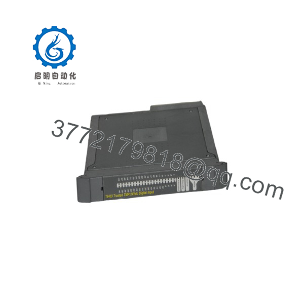
T8403
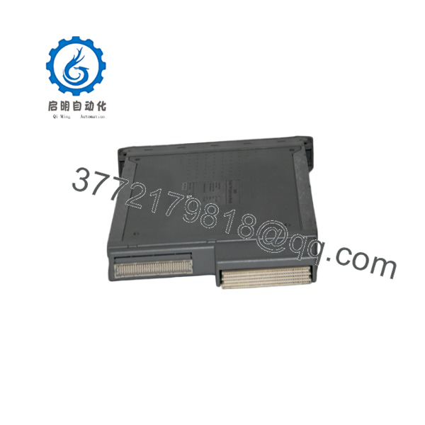
T8403
Installation & Configuration Guide
Stage 1: Pre-Installation
- Obtain the approved safety-system work permit and confirm that the work scope complies with the site safety lifecycle, management-of-change, proof-test, and bypass-control procedures.
- Identify whether the failed or replacement T8403 occupies a standard I/O slot, a dedicated Companion Slot, or a SmartSlot arrangement. Do not begin an online replacement unless the installed Trusted architecture and site procedure explicitly support it.
- Record the active and standby module positions, Trusted chassis number, slot number, module serial number, hardware revision, application revision, System.INI version, IEC 61131 Toolset project revision, and current module state.
- Record all safety-related alarms, diagnostic messages, field-input states, line faults, discrepancies, SOE records, bypasses, inhibited trips, active overrides, and operator actions before replacement.
- Verify that the affected field signals are safe to work on. Coordinate with operations because the T8403 can monitor emergency stops, permissives, valve-limit switches, flame-system contacts, turbine trips, gas-detection contacts, and other process-critical discrete signals.
- Apply lock-out/tag-out when the work requires field wiring or chassis power isolation. If an online replacement is formally approved, follow the exact Trusted system procedure and maintain the required Companion Slot or SmartSlot redundancy.
- Wear a grounded ESD wrist strap. The module contains static-sensitive electronic assemblies, and exposed connector pins must not be touched.
- Photograph the module front panel, chassis slot, field cable assembly, module labels, ejector positions, field termination arrangement, and any associated SmartSlot or Companion Slot cabling.
- Confirm the replacement module is , not another Trusted I/O type. Record its serial number and revision before installation.
- Inspect the replacement unit for housing damage, bent rear I/O connector pins, contamination, damaged ejectors, missing labels, or shipping damage. Do not install a module with bent pins, and do not attempt to straighten them.
Stage 2: Removal
- Confirm the module state and system architecture before opening the module ejectors. For a Companion Slot or SmartSlot replacement, verify that the standby or active partner module is healthy and properly recognized by the Trusted processor.
- If the module is not being replaced online, isolate chassis power and field circuits according to the approved safety-system shutdown procedure.
- Do not disconnect field wiring from memory. The field cable assembly and termination hardware are safety-system assets and must remain identified against approved drawings.
- Use the Trusted release key to open the module ejector tabs fully.
- Withdraw the evenly while supporting the module by the front fascia and ejectors. Avoid twisting the module, striking the rear connector, or applying side load to the chassis backplane.
- Protect the removed module immediately in ESD-safe packaging. Label it with the chassis and slot number, fault symptoms, diagnostic record, removal time, application revision, and asset number.
- Inspect the chassis connector and field cable assembly for bent contacts, contamination, damage, loose hardware, or incorrect keying. Correct the issue before installing the New Surplus module.
- Confirm that the field cable has the correct polarization. The official guidance specifies removal of cable keying pins 1, 3, and 5 for this module.
Stage 3: Installation
- Confirm the replacement label reads and verify the module revision is approved for the installed Trusted system and application baseline.
- Confirm that the compatible field cable assembly is installed and positioned correctly.
- Open the replacement module’s ejector tabs fully using the release key.
- Hold the module by its ejectors and carefully guide it into the intended chassis slot. The module should enter with minimal resistance.
- Push the module fully home by applying even pressure to the top and bottom of the front fascia.
- Close both ejectors until they click into their locked position. Do not force the module; if resistance occurs, remove it and inspect the connector pins and field cable keying.
- Do not remove the module housing or attempt board-level configuration. Physical configuration occurs through the Trusted engineering environment, not by modifying the module internals.
- Confirm that the controller recognizes the module and that its chassis/slot definition matches the approved I/O configuration.
- For an online changeover, observe module state progression and verify that the incoming module reaches the required educated or standby state before any active/standby transfer.
- Verify the field termination arrangement, SmartSlot link, and Companion Slot interface before returning the affected channel group to service.
Stage 4: Power-On & Testing
- Observe front-panel status indicators after installation. Confirm that the module reports healthy status and the expected active, standby, or educated operating mode.
- Review Trusted processor diagnostics and confirm that all three fault-containment regions report healthy status.
- Confirm that the module’s chassis and slot numbers in the Trusted application match the physical installation.
- Verify all 40 configured field inputs against expected plant conditions. Compare digital input status, numerical state, line-fault status, and measured input voltage with the field-device condition.
- Confirm that each channel reports the expected state. The module can distinguish open circuit, open contact, indeterminate, closed contact, short circuit, and unknown conditions.
- Test configured line-monitoring functions using the approved plant procedure. Do not simulate safety field faults without authorization from the safety-system owner.
- Verify SOE logging for any configured input channel by confirming that a controlled state change produces the expected event record with the required timestamp accuracy.
- Perform a documented functional test and, where applicable, the required partial proof test. Confirm that safety logic, alarms, shutdown actions, bypass management, and operator indications respond as designed.
- Remove temporary bypasses only under approved control, then obtain operations and safety-system-owner sign-off before returning the system to normal service.
- Record the replacement serial number, module revision, date, time, technician, application revision, test results, faults found, and updated buffer-stock quantity.
Firmware/Software Versions & Upgrade Notes
- Recommended firmware version: Keep the installed Trusted TMR processor firmware, System.INI configuration, Trusted Toolset project, and -approved hardware revision aligned with the validated safety application. The module is automatically configured by the Trusted TMR Processor after the application is downloaded and during Active/Standby changeover.
- No field DIP-switch configuration: The has no routine field DIP-switch or jumper setup for application behavior. Configure chassis and slot location, per-channel thresholds, line monitoring, LED behavior, noise filtering, and SOE settings through the Trusted engineering environment.
- Application configuration: The Trusted IEC 61131 Toolset defines I/O variables and module location. The Trusted System Configuration Manager defines channel thresholds, line monitoring, SOE behavior, and other module settings.
- Configuration records: Preserve the TMR Processor application backup, System.INI file, I/O module definition, channel mapping, line-monitor component details, SOE configuration, and complete safety validation record with the spare.
- Input-state logic: The module determines state by comparing measured input voltage with user-programmed thresholds. Incorrect threshold, field-supply, or line-monitoring configuration can misclassify an input as open, closed, shorted, or indeterminate.
- Online replacement requirement: Hot replacement depends on a properly engineered Companion Slot or SmartSlot configuration. Do not assume online replacement is available merely because a spare is present.
- Upgrade warning: Do not update Trusted processor firmware, Toolset version, System.INI, or safety application during an emergency module swap unless the existing baseline is unavailable and the site completes the required impact assessment, validation, and approval process.
- Downgrade warning: Do not load an older application, System.INI, or firmware baseline without confirming module-revision compatibility and establishing a validated recovery procedure. An uncontrolled downgrade can alter I/O interpretation, line-fault behavior, SOE records, or safety logic.
- Spare-control recommendation: Store each New Surplus in ESD-safe packaging with its serial number, verified hardware revision, compatible system baseline, field-cable requirement, chassis-keying record, proof-test procedure, and commissioning checklist.
Frequently Asked Questions (FAQ)
Are these really new units?
Yes. This inventory standard applies to New Original / New Surplus units only. A New Surplus should show no chassis insertion marks, connector-pin wear, damaged ejectors, altered labels, component rework, contamination, or evidence of prior field operation. Incoming QC should verify the model number, hardware revision, serial number, enclosure condition, rear connector pins, ESD-safe packaging, and approved functional-test documentation.
Why is New Surplus pricing lower than OEM new but higher than low-cost alternatives?
OEM-new pricing reflects current manufacturer channels, support contracts, and standard commercial terms. New Surplus pricing reflects the cost of securing, preserving, traceably validating, and warranting genuine safety-system hardware. Lower-cost alternatives can conceal connector wear, latent electronic faults, inconsistent hardware revisions, damaged isolation barriers, or incomplete functional testing. In a SIL 3 application, the relevant comparison is Total Cost of Ownership (TCO), including shutdown exposure, safety validation effort, process risk, and the cost of an extended safety-system outage.
Is the obsolete or EOL?
The remains documented by Rockwell Automation in an August 2021 product description, but documentation availability does not independently confirm current manufacturing status, regional stock, or future support commitments. Confirm lifecycle status directly through Rockwell Automation or an authorized source before making a long-term last-time-buy decision.
For a critical Trusted system, hold at least one tested on-site buffer stock unit. Keep a second unit only when the installed base is large, cross-site sharing cannot meet the required recovery time, or vendor lead time variability creates unacceptable safety-system downtime exposure.
Can I hot-swap the ?
Yes, but only in a properly engineered Trusted system that uses a dedicated Companion Slot or SmartSlot configuration. The official product description states that the can be hot-replaced online in those configurations.
Do not treat this as a routine plug-in replacement. Online work on a safety system requires approved procedures, confirmation of active and standby module health, controlled bypass management, trained personnel, and post-replacement validation.
Will replacing the module erase the safety application?
The safety application normally resides in the Trusted TMR Processor and engineering configuration, not solely in the . However, the module receives its configuration from the application and System.INI file. Back up the processor application, I/O mapping, thresholds, line-monitoring configuration, SOE settings, and safety validation records before replacement.
Do I need to rewire all 40 field inputs?
Normally, no. The connects through the existing Trusted field cable assembly and field termination arrangement. Keep field wiring intact unless troubleshooting identifies a cable, termination, or field-device fault. Verify that the field cable is correctly keyed for ; the module requires keying pins 1, 3, and 5 to be removed from the cable assembly.
What warranty and quality records should accompany this spare?
Specify a written 12month warranty, subject to ESD-safe storage, correct installation, and operation within the approved Trusted system. Require model, serial-number, and hardware-revision photographs; rear-pin inspection results; packaging verification; functional-test evidence; and final QC sign-off. Store those records with the safety asset file, application backup, proof-test procedure, and change-control documentation so the unit can be deployed quickly without weakening safety governance.



