
 WhatsApp: +86 16626708626
 Email:
  Phone: +86 16626708626
Description
Key Technical Specifications
| Parameter | Specification |
|---|---|
| Manufacturer | ICS Triplex / Rockwell Automation |
| Model | T8431 |
| Product Family | Trusted TMR |
| Module Type | 24 VDC Analog Input Module |
| Number of Inputs | 40 |
| Input Current Range | 0–22 mA |
| Input Voltage Range | 0–5.5 VDC |
| FTA Input Impedance | 250 Ω |
| Module Input Impedance | 16.967 kΩ |
| Resolution | 3.906 μA |
| Safety Accuracy | ±200 μA |
| Calibration Accuracy | ±0.15% |
| Backplane Supply | 20–32 VDC |
| Maximum Power | 20 W |
| SOE Resolution | 1 ms |
| SOE Timestamp Accuracy | ±10 ms |
| Operating Temperature | 0 °C to +60 °C |
| Storage Temperature | -25 °C to +70 °C |
| Relative Humidity | 10–95%, noncondensing |
| Dimensions | 266 × 31 × 303 mm |
| Weight | 1.149 kg |
These specifications are taken from Rockwell Automation’s PD-T8431 / ICSTT-RM273Q-EN-P documentation. The manual identifies T8431 specifically as a Trusted TMR 24 VDC analog input module with 40 channels.
Product Introduction
The ICS Triplex T8431 is a Trusted TMR 24 VDC analog input module providing 40 field-input channels for safety-related control systems. Each channel is processed through the module’s Triple Modular Redundant architecture, with automatic diagnostics and configurable line monitoring for open- and short-circuit field wiring faults.
The module supports 0–22 mA and 0–5.5 VDC input ranges, with 3.906 μA resolution and onboard Sequence of Events reporting at 1 ms resolution. It is designed for the Trusted T8000 architecture and supports online replacement through Companion Slot or SmartSlot arrangements when the system has been configured accordingly.
Installation & Configuration Guide
Stage 1 — Pre-Installation Preparation (~5 minutes)
- Apply LOTO procedures and follow the site’s safety-system maintenance procedure.
- Confirm that the replacement is specifically T8431, not another Trusted I/O module.
- Record the module revision and serial number.
- Photograph the existing installation and field-cable arrangement.
- Prepare ESD protection and the appropriate Trusted module release key.
- Confirm the applicable Trusted chassis, field cable, and FTA/VFTA configuration.
⚠️ Rockwell specifies that the module contains static-sensitive parts. Do not touch exposed connector pins or remove the module housing.
Stage 2 — Removing the Existing Module (~5 minutes)
- Verify the module’s operating state before removal.
- If configured with a Companion Slot or SmartSlot, verify which module is currently Active.
- Do not remove an Active module unless the system procedure specifically calls for an authorized changeover.
- Release the module ejector tabs.
- Withdraw the module carefully from the chassis.
- Inspect the rear connector for bent or damaged pins.
Rockwell’s manual explicitly states that an Active module should never simply be removed; Trusted systems can perform an Active/Standby changeover when the appropriate spare configuration is installed.
Stage 3 — Installing the Replacement (~5 minutes)
- Verify the T8431 model, revision, and serial information.
- Confirm that the field cable assembly is correctly installed.
- Open both module ejectors.
- Insert the into the intended Trusted chassis slot without forcing it.
- Press the upper and lower fascia areas until the module is fully seated.
- Close the ejectors until they lock.
- Verify that the module’s keying and field-cable arrangement match the installation.
The uses dedicated Trusted module keying; the manufacturer’s documentation specifies the keying configuration for this module.
Stage 4 — Power-On & Testing (~10–15 minutes)
- Restore system power according to the plant procedure.
- Observe the three Healthy indicators.
- Confirm the Active/Standby and Educated status.
- Verify all 40 channel indicators against expected field conditions.
- Check the System Configuration Manager configuration.
- Confirm chassis and slot assignment.
- Verify input values against calibrated field sources.
- Check line-monitoring status where enabled.
- Confirm SOE operation if the application uses Sequence of Events.
- Review module diagnostics before returning the safety function to normal service.
The Trusted processor automatically configures the input module after the application is downloaded, and the module provides dedicated health, Active/Standby, Educated, and channel-status indications.
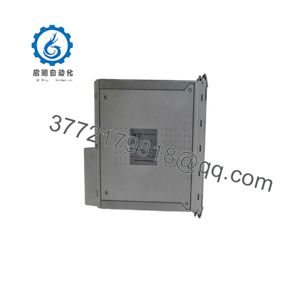
T8431
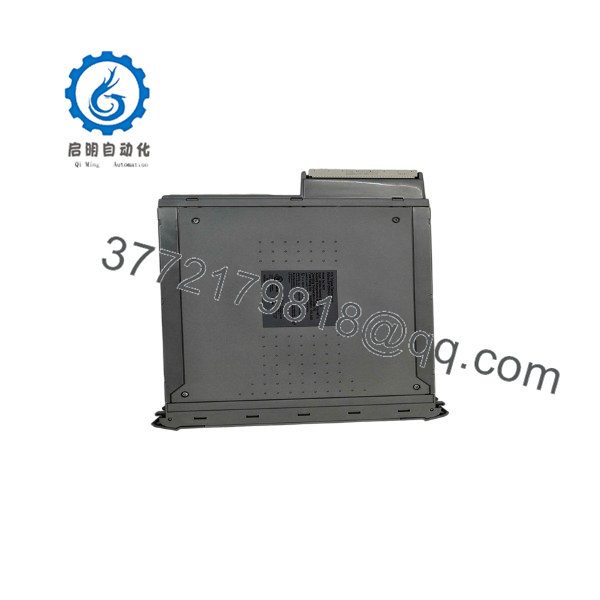
T8431
Frequently Asked Questions (FAQ)
Q1. What is the ICS Triplex ?
The is a Trusted TMR 24 VDC analog input module with 40 input channels. It interfaces field input devices to the Trusted safety-control architecture and provides per-channel diagnostics and line monitoring.
Q2. Is a 4–20 mA analog input module?
Yes. Its specified current input range is 0–22 mA, which accommodates standard 4–20 mA instrumentation. The specified voltage range is 0–5.5 VDC.
Q3. What does TMR mean in ?
TMR means Triple Modular Redundancy. The module contains three independent processing slices. Each of the 40 input channels is represented within the TMR architecture, allowing the system to detect faults and maintain valid input processing following a single internal fault.
Q4. Can the be hot-swapped?
Yes, when the Trusted system has been configured for an appropriate Companion Slot or SmartSlot arrangement. The manufacturer’s documentation describes automatic Active/Standby changeover and dedicated spare-module configurations. This does not mean that any can simply be pulled from an operating system without checking its Active/Standby state.
Q5. Does the require separate field power?
The module specification lists no dedicated Field Supply; its backplane/IMB supply is specified at 20–32 VDC, with a maximum power rating of 20 W. The exact field-loop power arrangement must still be checked against the installed FTA and external instrumentation.
Q6. How should a replacement be configured?
The physical module itself does not require conventional DIP-switch configuration. Rockwell states that configurable characteristics are handled through the Engineering Workstation/System Configuration Manager and become part of the application or System.INI configuration loaded to the TMR Processor.
Q7. What should procurement verify before ordering a ?
Verify the exact model, hardware revision, condition, serial/traceability information, included field-interface hardware, and test status. For an installed safety system, also confirm compatibility with the existing Trusted chassis, field cable, FTA/VFTA, application configuration, and spare-module architecture. Do not substitute another Trusted I/O model simply because its physical dimensions appear similar.



