WhatsApp: +86 16626708626
 Email:
 Phone: +86 16626708626
Description
Core Product Summary
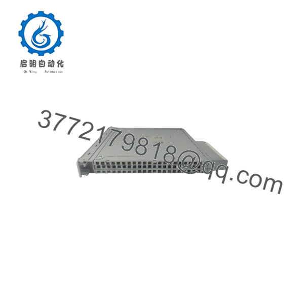
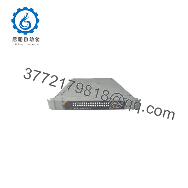
The ICS Triplex T8431C is a Series C, conformal-coated Trusted TMR 24 Vdc analog input module providing 40 fault-tolerant input channels for the Rockwell Automation (ICS Triplex) Trusted Triple Modular Redundant safety platform. Each of the 40 field inputs is measured through three independent module slices (A, B, C), so a fault on one slice is contained without affecting the other two. The module acts as a current sink for sourcing field devices and supports 4-20 mA signal handling through a standard field termination assembly.
Integration centers on the Trusted chassis: the module installs in Trusted Controller Chassis I/O slots 1-8 or Trusted Expander Chassis slots 1-12 (chassis 1-15 per system addressing), communicates with the TMR Processor across the Inter-Module Bus (IMB), and is configured entirely from the engineering workstation through the IEC 61131 TOOLSET and Trusted System Configuration Manager. Per-channel line monitoring detects open and shorted field cables, and onboard Sequence of Events reporting resolves state changes to 1 ms. The module is TÜV certified to IEC 61508 SIL 3 and supports online hot replacement via Companion Slot or SmartSlot configurations.
Key Technical Specifications
| Parameter | Value |
|---|---|
| Product type | Trusted TMR 24 Vdc analog input module, 40 channel |
| Series / variant | Series C, conformal coated (order code T8431C) |
| Redundancy architecture | Triple Modular Redundant (TMR), three slices (A, B, C) per module |
| Input channels | 40 TMR analog input channels per module |
| Field device interface | Sourcing field input devices; module acts as current sink |
| Signal conditioning | Field current converted to voltage via 250 Ω resistor on standard FTA |
| Threshold definition | 4 configurable + 2 fixed thresholds per channel, with hysteresis |
| Diagnostics | Comprehensive automatic diagnostics and self-test per input channel |
| Line monitoring | Selectable per channel; detects open-circuit and short-circuit field wiring |
| Isolation | 2500 V impulse withstand opto/galvanic isolation barrier |
| Sequence of Events | Onboard SOE reporting, 1 ms event resolution |
| Analog conversion | ΣΔ (sigma-delta) input circuit per channel on each slice |
| Engineering unit scaling | Reported as 1024 counts per volt; 4-20 mA maps to -1024 to 4096 counts (250 Ω loop) |
| Safety certification | TÜV certified to IEC 61508 SIL 3 |
| Online replacement | Hot-replace via dedicated Companion (adjacent) Slot or SmartSlot |
| Front panel indication | Per-channel input status LEDs; module status LEDs (Active, Standby, Educated) |
| Module construction | Host Interface Unit (HIU), Field Interface Unit (FIU), Field Termination Unit (FTU), Front Panel Unit (FPU) |
Detailed Product Overview
Within a Trusted system, the T8431C sits between the field devices and the TMR Processor. It is a high-integrity I/O module: every one of the 40 analog inputs is acquired independently by three module slices, and the processor receives majority-voted data. Each slice is a Fault Containment Region, with isolation between slices designed so that a fault on one slice does not disturb the operation of the other two. For an engineer specifying safety-related analog acquisition, this triplicated, voted path is the module’s defining characteristic: a single component failure degrades a channel to two-out-of-three operation rather than silently corrupting the measured value.
The measurement chain itself is deliberately short. Each field input on each slice feeds a sigma-delta input circuit whose output naturally toggles between on and off states; a failed circuit saturates stuck-on or stuck-off, which the module detects automatically. Because the analog path involves few components, an analog failure is contained to a single channel on a single slice instead of disabling a group of channels. The module compares the measured field voltage against four user-programmed thresholds plus fixed minimum and maximum thresholds, producing multiple threshold bands. The reported channel state therefore carries more information than a raw analog number: states distinguish underrange, line fault, low, normal, high, high-high, overrange, and an “Unknown” value raised when two or more slices cannot be measured consistently or a 2oo3 channel discrepancy is detected.
Per-channel line monitoring adds wiring-level diagnostics. When configured, the module detects open and shorted field cables on each channel independently, and the front-panel LEDs report both input status and wiring-fault status per channel. This matters in commissioning and maintenance: field wiring problems are visible at the module rather than only as unexplained process values. If the field supply voltage and return are wired to the module’s auxiliary input channels, thresholds can be specified as a ratio of the field supply voltage, which keeps trip boundaries consistent when the supply drifts.
State changes are timestamped by the module’s onboard real-time clock with 1 ms SOE resolution, and each input can be included in or excluded from the system SOE log. This supports post-event analysis at a resolution fine enough to reconstruct event order across a trip sequence.
A documented operational consideration applies to Series C hardware: a Rockwell Automation product notice (2025-08-002) describes a potential anomaly in which Trusted T8431C Series C input modules may experience a slice shut down. Engineers planning an installation or a changeover to Series C modules should review the current product notice and associated guidance as part of the engineering change process.
T8431C
T8431C
System Compatibility & Integration Requirements
| Item / Dependency | Verified Compatibility or Requirement | Practical Note |
|---|---|---|
| Host system | Trusted TMR system; module communicates with the Trusted TMR Processor | All Trusted I/O modules interface to the Inter-Module Bus (IMB), which also supplies power |
| Chassis / slots | Trusted Controller Chassis I/O slots 1-8; Trusted Expander Chassis slots 1-12; chassis addressed 1-15 (controller = 1) | Module position declared via OEM parameters TICS_CHASSIS and TICS_SLOT |
| Module replacement topology | Dedicated Companion (adjacent) Slot or SmartSlot (one spare slot serving many modules) | Enables online hot replacement; SmartSlot link coordinates Active/Standby changeover |
| Field cabling | Trusted I/O Companion Slot cables (ICSTT-RM311) or SmartSlot cables (ICSTT-RM313) | Same publications detail the FTA / VFTA types usable with this module |
| Field termination | Standard Field Termination Assembly (FTA) or Versatile FTA (VFTA) | 250 Ω loop resistor on the standard FTA converts 4-20 mA to the measured voltage |
| Configuration tools | IEC 61131 TOOLSET (Dictionary Editor, I/O Connection Editor) plus Trusted System Configuration Manager | No configuration is performed on the physical module; settings load via the TMR Processor as part of the application or System.INI file |
| Keying / polarization | Module keyed at manufacture; for T8431 remove cable keying pins 1, 4, and 5 | Both keying strips must be polarized for Companion Slot cable installations |
| Software data interface | T8431 Complex Equipment Definition: 8 I/O boards (THRSHIN, STATE, AI, THRSHOUT, LINE_FLT, DISCREP, HKEEPING, INFO) | Application reads per-channel state, engineering units, line fault status, discrepancy, and housekeeping registers |
| Safety documentation | Trusted TMR Safety Manual T8094 (ICSTT-RM459) | Defines the requirements to verify safety objectives at each stage of the system lifecycle |
Dimensions, Mounting & Connection Notes
Mounting follows the standard Trusted I/O module procedure. Before installation, inspect the housing for damage and check the rear I/O connector for bent pins; a module with bent pins must not be installed, and pins must not be straightened. The module contains static-sensitive parts: observe static-handling precautions, do not touch exposed connector pins, and never remove the module housing. Record the module type, revision, and serial number before installation.
Installation sequence: confirm the field cable assembly is fitted and correctly located; release the ejector tabs with the release key so they are fully open; insert the module holding the ejectors; press it fully home at the top and bottom of the fascia; then close the ejectors until they click into their locked position. The module should seat with minimal resistance — never force it. Field connections are made at the rear of the chassis through the Field I/O Cable Assembly mating with the module’s FTU field connector; the field connector pin-out carries the 40 channel inputs (positive terminals with shared returns) plus the three SmartSlot link contacts. The module is keyed to prevent insertion in the wrong chassis position, and the integrator must key the cable by removing keying pieces to match the module — for this module type, keying pins 1, 4, and 5 are removed; both keying strips must be polarized on Companion Slot cable installations.
FAQ
What is the ICS Triplex T8431C?
The T8431C is a Series C, conformal-coated Trusted TMR 24 Vdc analog input module with 40 Triple Modular Redundant input channels, part of the Trusted I/O module range for the Trusted TMR safety platform.
What does the T8431C do?
It acquires up to 40 sourcing analog field inputs as a current sink, measures each input through three independent slices with majority voting, performs automatic diagnostics and per-channel line monitoring, and reports channel states and sequence-of-events data to the Trusted TMR Processor.
Which chassis does the T8431C install in?
It installs in Trusted Controller Chassis I/O slots numbered 1-8 and Trusted Expander Chassis I/O slots numbered 1-12, with chassis addressed 1-15 in the system configuration (the controller chassis is chassis 1).
Is the T8431C certified for safety applications?
Yes, the module is TÜV certified to IEC 61508 SIL 3.
Can the T8431C be replaced while the system is running?
Yes, the module supports online hot replacement using a dedicated Companion (adjacent) Slot or SmartSlot configuration, with the SmartSlot link coordinating the Active/Standby changeover.
How is the T8431C configured?
No configuration is performed on the physical module. Channel thresholds, line monitoring, LED modes, and noise filtering are defined in the IEC 61131 TOOLSET and the Trusted System Configuration Manager, then loaded into the TMR Processor as part of the application or System.INI file, which automatically configures the module.
How does the T8431C handle 4-20 mA signals?
Field current is converted to voltage through a 250 Ω resistor on the standard field termination assembly. The module reports engineering units at 1024 counts per volt, so a 4-20 mA loop spans -1024 to 4096 counts, which can be scaled directly in the application.
What wiring faults can the T8431C detect?
With per-channel line monitoring enabled, the module detects open-circuit and short-circuit field wiring faults on each configured channel and indicates them on the front-panel channel LEDs.
Documented Performance Data
| Metric | Value | Condition |
|---|---|---|
| Sequence of Events event resolution | 1 ms | Onboard SOE reporting; state change triggered by configurable per-channel voltage thresholds |
| Input state determination | Majority-voted (2oo3) across three slices | Channel reports “Unknown” if two or more slices cannot be measured or a 2oo3 discrepancy is detected |
| Isolation barrier impulse withstand | 2500 V | Opto/galvanic isolation between module sections and field interface |
| Engineering unit reporting | 1024 counts per volt | 250 Ω FTA loop; 4-20 mA corresponds to -1024 to 4096 counts |