WhatsApp: +86 16626708626
 Email:
 Phone: +86 16626708626
Description
Core Product Summary
The ICS Triplex T8451C is a Series C, conformal-coated Trusted TMR 24 Vdc digital output module providing 40 fault-tolerant output points for the Rockwell Automation (ICS Triplex) Trusted Triple Modular Redundant safety platform. Each output drives its load through three fully monitored fail-safe switch channels — one stage resident on each of the module’s three slices — so the failure of any single switch or an entire slice still leaves two switch channels able to control the load.
The module performs triplicated diagnostics throughout, measuring current and voltage on every portion of each voted output channel and testing for stuck-on and stuck-off failures. Automatic per-point line monitoring detects open and short circuits in field wiring and load devices, automatic overcurrent protection is built in per channel, and outputs are powered in isolated groups of eight (Power Groups) with Group Fail-Safe Switches that de-energize a group if two or more module faults are detected. Onboard Sequence of Events reporting resolves output state changes to 1 ms. The module is TÜV certified to IEC 61508 SIL 3 and is not approved for direct connection to hazardous areas — intrinsic safety barrier devices are required for such installations.
Key Technical Specifications
| Parameter | Value |
|---|---|
| Product type | Trusted TMR 24 Vdc digital output module, 40 channel |
| Series / variant | Series C, conformal coated (order code T8451C) |
| Redundancy architecture | Triple Modular Redundant (TMR), three slices (A, B, C) per module |
| Output points | 40 TMR digital output points per module |
| Output switch structure | Three monitored fail-safe (6-element) switch channels per load, one per FIU slice |
| Output classification | Protected outputs per IEC 61131-2 (‘Protected Outputs Requirements’) |
| Overcurrent protection | Automatic, per channel; no external fuses required; non-replaceable fusible link for absolute protection |
| Line monitoring | Automatic per point; detects open-circuit and short-circuit field wiring and load faults |
| De-energized short-circuit detection | Optional, via System.INI configuration; detects load resistance below 24 Ω |
| Field supply grouping | Outputs powered in isolated groups of eight (Power Groups) with Group Fail-Safe Switches (GFSS) |
| Diagnostics | Triplicated tests for current, voltage, stuck-on and stuck-off failures; Safety Layer Test (SLT) and CRC checks commanded by the TMR Processor |
| Isolation | 2500 V impulse withstand opto/galvanic isolation barrier |
| Sequence of Events | Onboard SOE reporting, 1 ms event resolution |
| Supply monitoring | Two additional ΣΔ circuits per slice optionally monitor the external field I/O supply voltage |
| Safety certification | TÜV certified to IEC 61508 SIL 3 |
| Hazardous area use | Not approved for direct connection; must be used with Intrinsic Safety Barrier devices |
| Online replacement | Hot-replace via dedicated Companion (adjacent) Slot or SmartSlot |
| Front panel indication | Per-point output status LEDs; module status LEDs (Active, Standby, Educated, Slice Healthy) |
| Module construction | Host Interface Unit (HIU), Field Interface Unit (FIU), Field Termination Unit (FTU), Front Panel Unit (FPU) |
Detailed Product Overview
In a Trusted system, the T8451C is the final control element between the safety logic and the field loads — typically solenoid valves, relays, and other 24 Vdc actuation devices in safety instrumented functions. Its engineering purpose is different from an input module’s: it must guarantee that a commanded load can be both energized and, critically, de-energized even while internal faults accumulate. The output switch structure addresses this directly. Each load is driven through a TMR switch topology of three fully monitored fail-safe switch channels, one physically resident on each of the module’s three Field Interface Units. Switches are built from enhancement-mode MOSFETs that are guaranteed off in the absence of module power, and any single switch or entire slice failure leaves two of the three switch channels operational to power or drop the load.
Switch health is verified continuously without interrupting the load. Gate voltages of the on-state switches are modulated one at a time, and the local digital signal processors analyze the resulting small AC monitoring signals to determine each switch’s on-resistance and threshold voltage, while the other two channels carry the load current. Output current is monitored while energized, and a sustained overcurrent condition latches a short-circuit fault state and de-energizes the output; the latched fault can be cleared by the system Fault Reset button or by a commanded state transition. While de-energized, optional System.INI-configured short-circuit detection partially energizes the field circuit — constrained to less than 2 V or 100 mA — to measure channel load resistance and flag values below 24 Ω.
The Power Group concept is the module’s second fail-safe layer. Outputs are powered in isolated groups of eight, each group served by a Group Fail-Safe Switch composed of three parallel elements, one associated with each slice. Any slice that observes an output failing to de-energize can command the GFSS elements; two or more faults within the module cause the Group Fail-Safe Switches to de-energize the entire group. The GFSS bias is driven by a charge pump from the slice comms clock, so loss of communication or a slice watchdog timeout also collapses the bias and de-energizes the group.
State reporting is granular enough for loop-level troubleshooting: each channel reports a numerical output state and a line fault status distinguishing field short circuit, output energized, no-load/open circuit, output de-energized, and no field supply voltage. Unused outputs should be commanded off in the application and wired through a 4.7 kΩ 0.5 W resistor to zero volts so that a current exceeding the NO-LOAD threshold flows, preventing nuisance NO-LOAD faults. Every output state change is timestamped with 1 ms resolution for the system SOE log.
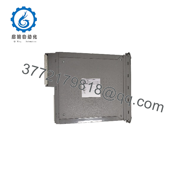
T8451C
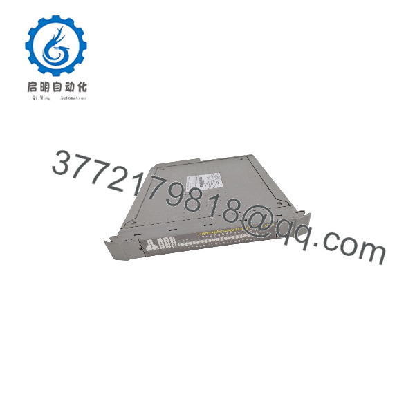
T8451C
System Compatibility & Integration Requirements
| Item / Dependency | Verified Compatibility or Requirement | Practical Note |
|---|---|---|
| Host system | Trusted TMR system; module communicates with the Trusted TMR Processor across the Inter-Module Bus (IMB) | The IMB also supplies module power; HIU shares the dual 24 Vdc chassis supply redundantly |
| Series C identification | T8451C is the Series C (conformal-coated) variant; Rockwell’s Series C I/O documentation lists T8451C revision C units from January 2023 with a minimum system requirement of T2301 and later | Module revision is identified on the module nameplate; check the current Rockwell Series C documentation before planning a changeover |
| Field cabling | Trusted I/O Companion Slot cables (ICSTT-RM311) or SmartSlot cables (ICSTT-RM313) | The same publications detail the FTA / VFTA types usable with this module |
| Field termination | Field Termination Assembly (FTA) or Versatile FTA (VFTA) | Custom length multi-core FTA cables: 0.5 mm², 40 Ω/km (a 50 m cable ≈ 4 Ω loop impedance, ≈ 2 Vdc drop at 0.5 A) |
| Field supply wiring | Power Group positive and return per group of eight outputs, per the field connector pinout | Two ΣΔ circuits per slice optionally monitor the external field supply voltage |
| Module replacement topology | Dedicated Companion (adjacent) Slot or SmartSlot (one spare slot for many modules) | SmartSlot link coordinates Active/Standby changeover during online hot replacement |
| Configuration | Channel behavior (e.g., de-energized short-circuit detection) configured via the System.INI file loaded into the TMR Processor | No physical configuration is performed on the module itself |
| Hazardous area integration | Not approved for direct connection to hazardous areas | Must be used with Intrinsic Safety Barrier devices |
| Safety documentation | Trusted TMR Safety Manual (T8094, publication ICSTT-RM459) | Requirements for verifying safety objectives at each stage of the safety system lifecycle |
| Companion documentation | Trusted Sequence of Events and Process Historian Package description (ICSTT-RM243) | Full SOE configuration details for per-output SOE logging |
Dimensions, Mounting & Connection Notes
Before installation, visually inspect the module housing for damage and check the rear I/O connector for bent pins. A damaged module or one with bent pins must not be installed, and bent pins must never be straightened — return the module for replacement. The module contains static-sensitive parts: observe static-handling precautions, do not touch exposed connector pins, and do not remove the module housing under any circumstances. Record the module type, revision, and serial number before installation.
Installation sequence: confirm the field cable assembly is installed and correctly located; verify that any I/O module keys are installed in the correct positions and properly seated; release the ejector tabs with the release key until fully open; insert the module while holding the ejectors; press it fully home at the top and bottom of the fascia; and close the ejectors until they click into the locked position. The module should seat with minimal resistance — never force it.
Field connections are made through the FTU field connector, which mates with the Field I/O Cable Assembly at the rear of the Trusted Controller or Expander Chassis. The pin-out carries the 40 channel positive outputs arranged in Power Groups of eight, each with its own group positive and return, plus the three SmartSlot link contacts. All Trusted modules are keyed at manufacture to prevent insertion into the wrong chassis position; the integrator keys the associated cable to match. During operation, all three front-panel Healthy indicators should be green; a flashing red Healthy indicator signals a fault that should be investigated, and if the cause is within the module it should be replaced using the configured Companion Slot or SmartSlot arrangement.
FAQ
What is the ICS Triplex T8451C?
The T8451C is a Series C, conformal-coated Trusted TMR 24 Vdc digital output module with 40 Triple Modular Redundant output points, part of the Trusted I/O module range for the Trusted TMR safety platform.
What does the T8451C do?
It provides fault-tolerant switching for up to 40 field loads: each output is driven through three monitored fail-safe switch channels, with triplicated diagnostics, automatic per-point line monitoring, per-channel overcurrent protection, and Group Fail-Safe Switches covering each group of eight outputs.
How does the T8451C tolerate a failed output switch or slice?
Each load is driven by three switch channels, one on each module slice. Any single switch or entire slice failure leaves the other two switch channels able to power the load, and the TMR architecture allows normal output control to continue after the first fault occurrence.
Does the T8451C need external fuses?
No. Each channel has automatic overcurrent protection, which latches and de-energizes the output on a sustained overcurrent; an internal non-replaceable fusible link provides absolute protection.
What field wiring faults can the T8451C detect?
Automatic line monitoring on every point detects open-circuit and short-circuit faults in field wiring and load devices, both while energized and — when configured via the System.INI file — while de-energized, by measuring load resistance below 24 Ω.
Can the T8451C be used in hazardous areas?
No, the module is not approved for direct connection to hazardous areas and must be used in conjunction with Intrinsic Safety Barrier devices.
Can the T8451C be replaced while the system is running?
Yes, the module supports online hot replacement using a dedicated Companion (adjacent) Slot or a SmartSlot, with the SmartSlot link coordinating the Active/Standby changeover.
How should unused outputs be handled?
Command them off in the application and wire each through a 4.7 kΩ 0.5 W resistor to zero volts so the drawn current exceeds the NO-LOAD threshold and prevents NO-LOAD fault signaling.
What safety certification does the T8451C hold?
The module is TÜV certified to IEC 61508 SIL 3.
Documented Performance Data
| Metric | Value | Condition |
|---|---|---|
| Sequence of Events event resolution | 1 ms | Onboard SOE reporting; output state changes timestamped by the module’s onboard timer |
| Output state determination | Automatic voltage and current measurement per channel | Five reported states: field short circuit, output energized, no-load/open circuit, output de-energized, no field supply voltage |
| De-energized short-circuit detection threshold | Load resistance < 24 Ω | Optional System.INI configuration; partial energizing constrained to < 2 V / < 100 mA |
| FTA cable loop impedance | 0.5 mm² conductor, 40 Ω/km | A 50 m custom multi-core FTA cable ≈ 4 Ω loop, ≈ 2 Vdc drop at 0.5 A |
| Isolation barrier impulse withstand | 2500 V | Opto/galvanic isolation barrier |
| Isolated serial link rate | 6.25 Mbit/sec | Between each FIU slice and its HIU slice |