
 WhatsApp: +86 16626708626
 Email:
  Phone: +86 16626708626
Description
Key Technical Specifications
| Parameter | Value |
|---|---|
| Manufacturer | ICS Triplex / Rockwell Automation |
| Model Number | T9110 |
| Product Series | AADvance 9000 Series |
| Product Type | Safety controller processor module |
| Primary Function | Executes control application, manages I/O communication, diagnostics, and safety-system functions |
| Nominal Supply | 24 V DC |
| Permitted Supply Range | 18–32 V DC |
| Typical Power Consumption | 8 W |
| Ambient Operating Temperature | −25 to +60°C (−13 to +140°F) |
| System Architecture | AADvance controller platform |
| Controller Role | Main processor module for the AADvance safety controller |
| I/O Interface | Communicates with compatible AADvance I/O modules through the controller system architecture |
| Typical Applications | Safety instrumented systems, emergency shutdown, fire and gas, burner management, turbine protection, and critical process control |
| Configuration Environment | AADvance-Trusted SIS Workstation / approved Rockwell Automation engineering environment |
| Hardware Revision Control | Confirm the exact hardware revision against the existing controller, approved project baseline, and Rockwell compatibility documentation |
| Lifecycle Status | Safety-critical installed-base spare; confirm current regional lifecycle, firmware support, and cybersecurity status with Rockwell Automation before a last-time-buy decision |
| Stocking Recommendation | Min: 1 exact verified processor per plant or recoverable controller population; Max: 2 only when separate systems cannot share a spare within the required safety-system recovery window |
Rockwell Automation’s AADvance Controller System Build Manual lists T9110 as a processor module with an 18–32 V DC operating range, 8 W power consumption, and a −25 to +60°C ambient operating range.
Product Introduction & Supply Chain Strategy
The ICS Triplex T9110 is an AADvance safety-controller processor module. It runs the approved control and safety application, coordinates I/O communications, manages diagnostics, and supports safety functions used in shutdown, interlock, emergency-stop, fire-and-gas, and critical process-control applications. It belongs to the AADvance 9000 Series controller platform, not the separate Trusted TMR processor family.
This product is a Brand New Surplus unit. It is not used, not pulled from a decommissioned plant, and not refurbished. All modules undergo rigorous quality verification to ensure OEM-level reliability. For a safety controller, one configured on-site buffer stock processor provides high ROI because recovery depends on more than hardware availability. The spare must be controlled with a validated application backup, software version record, hardware revision record, cybersecurity review, and documented commissioning procedure.
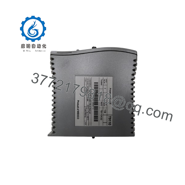
T9110
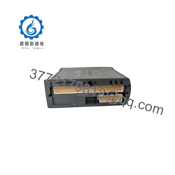
T9110
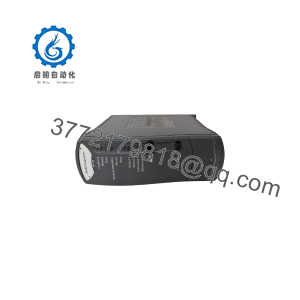
T9110
Installation & Configuration Guide
Stage 1: Pre-Installation
- Obtain an approved safety-system work permit, management-of-change authorization, and operations approval before replacing the T9110.
- Confirm the affected AADvance controller’s safety function, protected equipment, permissives, shutdown actions, bypasses, inhibits, overrides, communications interfaces, and current operating state.
- Record the controller asset number, rack location, processor slot, T9110 serial number, hardware revision, installed software issue, application revision, controller configuration, network settings, and current diagnostic state.
- Back up the current AADvance controller application, configuration database, safety validation record, communications settings, time synchronization settings, and approved firmware baseline before touching hardware.
- Record active alarms, diagnostic history, fault indicators, watchdog status, I/O module states, safety bypasses, forced values, event logs, and controller communication status.
- Determine whether the controller architecture includes processor redundancy or another approved recovery arrangement. Do not assume that a spare T9110 alone enables online replacement.
- Place the process in an approved safe state before removal unless the site’s validated safety procedure explicitly permits a controlled online replacement.
- Apply lock-out/tag-out to controller power and related control circuits if the procedure requires power isolation.
- Verify the 24 V DC control-power supply is within the permitted 18–32 V DC range and investigate any evidence of undervoltage, ripple, grounding faults, loose terminals, or power-supply instability.
- Wear a grounded ESD wrist strap and work with ESD-safe handling controls.
- Photograph the controller assembly, slot position, module labels, power connections, I/O interfaces, network connections, grounding, and adjacent module arrangement.
- Verify the replacement is an exact processor module with an approved hardware revision. Do not substitute a Trusted T8110/T8111 processor or another ICS Triplex controller module; those products use different architectures.
Stage 2: Removal
- Confirm the controller is in the approved maintenance or safe state and that operations has acknowledged any loss of safety-system availability.
- If power isolation is required, remove controller power and verify the DC supply is absent before disconnecting the module.
- Do not disconnect external wiring from memory. Preserve all connector and cable identification against approved drawings and photographs.
- Release the module using the specified retaining hardware or ejector mechanism. Support the module during removal and prevent side loading on backplane connectors.
- Remove the evenly from its slot. Do not twist the module, force it against adjacent hardware, or touch exposed connector pins.
- Inspect the mating connector, card guide, slot hardware, grounding contacts, and surrounding controller assembly for bent contacts, contamination, heat damage, corrosion, or loose retaining hardware.
- Inspect adjacent power-supply and I/O modules for fault indicators. A processor fault can be secondary to unstable 24 V DC supply, communication errors, overheating, grounding problems, or an external network issue.
- Place the removed processor in ESD-safe packaging and label it with asset number, serial number, hardware revision, software issue, failure symptoms, diagnostic history, removal date, and application-backup reference.
Stage 3: Installation
- Compare the replacement label against the removed module and approved system baseline. Verify model number, serial number, hardware revision, and any manufacturing or regulatory markings.
- Confirm that the slot is clean, dry, undamaged, and free of debris. Do not attempt to bend or repair damaged backplane contacts.
- Align the New Surplus with the controller guides and insert it evenly into the designated processor slot.
- Seat the module fully using only the approved insertion points. Do not press on labels, connectors, components, or exposed circuit areas.
- Engage all retaining clips, ejectors, screws, or latches fully.
- Restore any connectors, grounding hardware, shielding, and cable restraints exactly as documented.
- Confirm that the 24 V DC controller supply, grounding arrangement, network cabling, and I/O interfaces match the approved installation drawing.
- Do not change adjacent I/O modules, controller wiring, network hardware, firmware, or application settings during a direct processor replacement unless a separate approved change request covers those items.
- Ensure that the approved application backup, configuration files, software tools, and recovery media are immediately available before powering the controller.
Stage 4: Power-On & Testing
- Measure the controller supply before energizing. Confirm the receives a stable supply within the 18–32 V DC operating range.
- Apply power according to the approved safety-system startup procedure and observe controller startup indicators, diagnostics, and communications status.
- Confirm that the controller recognizes the correctly and that it reports the expected hardware revision, processor state, and diagnostic status.
- Restore the approved application and configuration only if required by the documented recovery procedure. Verify file versions before download.
- Confirm that the application checksum, controller configuration, I/O mapping, network addresses, time synchronization, communications paths, and safety logic revision match the validated baseline.
- Verify all safety I/O status, communications links, diagnostics, alarm annunciation, bypasses, forced values, and protective functions before enabling normal process operation.
- Perform the required functional test, partial proof test, or full proof test according to the site safety lifecycle procedure. Test only approved functions and coordinate every test with operations.
- Confirm the controller correctly executes shutdown, permissive, interlock, alarm, and reset behavior for the affected safety functions.
- Remove temporary bypasses or inhibits under approved control. Obtain operations and safety-system-owner approval before returning the application to normal operation.
- Record the replacement processor serial number, hardware revision, software issue, application revision, test records, work authorization, installation time, technician, and remaining buffer-stock quantity.
Firmware/Software Versions & Upgrade Notes
- Recommended firmware version: Use the same validated software issue and AADvance application baseline as the removed processor whenever possible. The recovery target is the plant’s approved and tested software version, not the newest version available.
- Configuration requirement: Maintain a controlled copy of the AADvance controller project, application source files, compiled application, configuration database, communication settings, network parameters, security configuration, validation records, and recovery instructions.
- Hardware revision compatibility: Verify that the New Surplus hardware revision is approved for the installed AADvance system software issue. A processor may fit mechanically but require a specific software release, configuration utility version, or hardware-support package.
- Power-supply requirement: The operates from 18–32 V DC and is listed at 8 W power consumption. Confirm the controller’s 24 V DC supply capacity, voltage stability, grounding, and protective coordination before commissioning.
- Backward compatibility: An older processor software issue may not recognize newer I/O module revisions, network interfaces, security features, or project files created with later engineering software.
- Forward compatibility: A later AADvance software or firmware release can require application conversion, I/O validation, cybersecurity review, regression testing, safety validation, and documentation updates. Do not treat it as a routine spare installation.
- Upgrade warning: Do not upgrade processor firmware, engineering-tool versions, or controller application during an emergency hardware swap unless the installed baseline is unavailable and the site completes the required impact assessment, test plan, validation, and approval.
- Downgrade warning: Do not load an older firmware image or application backup without confirming compatibility with the replacement processor hardware revision and installed I/O modules. An uncontrolled downgrade can alter controller behavior, communications, diagnostics, or safety timing.
- Product notice review: Rockwell Automation publishes product notices that can apply to Trusted, AADvance, and AADvance Eurocard product families. Review applicable notices for the exact installed product revision before returning a safety controller to service.
- Spare-control recommendation: Store the processor in ESD-safe packaging with verified hardware revision, controller software baseline, application checksum, current configuration backup, site commissioning checklist, and safety-system recovery procedure.
Frequently Asked Questions (FAQ)
Are these really new units?
Yes. This inventory policy applies only to New Original / New Surplus modules. A New Surplus should show no installation marks, damaged connectors, altered labels, board-level repairs, contamination, heat discoloration, corrosion, or missing traceability markings. Incoming inspection should verify the model number, serial number, hardware revision, enclosure condition, connector condition, ESD-safe packaging, and available quality-verification records.
Why is New Surplus pricing lower than OEM new but higher than lower-cost alternatives?
OEM-new pricing reflects active manufacturer channels, support commitments, and standard commercial terms. New Surplus pricing reflects the cost of locating, verifying, preserving, and warranting genuine safety-controller inventory. Lower-cost alternatives can hide hardware-revision mismatch, poor storage conditions, connector damage, latent electronic faults, incomplete traceability, or unverified software compatibility. For a safety controller, the correct financial comparison is Total Cost of Ownership (TCO), including process risk, validation effort, shutdown duration, lost production, and regulatory exposure.
Is the obsolete or EOL?
Rockwell Automation continues to identify in AADvance system documentation and product-notice resources, but published documentation does not independently confirm current manufacturing status, regional availability, or future support duration. Confirm lifecycle status, hardware revision support, and authorized supply availability with Rockwell Automation before making a major last-time-buy decision.
For a critical safety controller, keep one verified processor on-site. Consider a second unit only if multiple independent controllers use the same approved hardware revision, cross-site sharing cannot meet recovery requirements, and the expected outage cost exceeds the annual carrying cost.
Can I hot-swap the ?
Do not assume hot-swap capability. Whether a processor can be replaced online depends on the exact AADvance controller architecture, processor redundancy design, installed firmware, application configuration, and approved plant safety procedure. Treat the as requiring a planned safety-system maintenance activity unless the site’s validated documentation explicitly authorizes online replacement.
Will replacing the erase the safety application?
It can require application restoration, depending on the controller architecture, processor state, storage arrangement, and recovery procedure. Always maintain a verified application backup and configuration record before replacement. Confirm the application checksum, I/O mapping, network settings, safety logic revision, and controller diagnostics after installation before returning the system to service.
Can I substitute a Trusted TMR processor or another ICS Triplex CPU?
No. Do not substitute a Trusted T8110/T8111 processor, a different AADvance controller module, or a similarly named ICS Triplex product without a formal engineering-approved migration plan. The belongs to the AADvance platform, while Trusted TMR products use a different controller architecture, configuration method, I/O ecosystem, and safety validation basis.
What warranty and quality documentation should accompany this spare?
Specify a written 12month warranty, subject to correct ESD-safe storage, installation, and operation within the approved AADvance architecture. Require model, serial-number, and hardware-revision photographs; connector inspection records; packaging verification; controlled power-on or functional-test evidence where appropriate; and final QC sign-off. Store those records with the safety asset file, application backup, validation documentation, and recovery plan so the processor can be deployed quickly without compromising safety governance.



