
 WhatsApp: +86 16626708626
 Email:
 Phone: +86 16626708626
Description
Core Product Summary (Brand / Model / Key Attributes)
The ICS Triplex T9310-02 is a factory-terminated 2-meter I/O bus expansion cable assembly for the Rockwell Automation AADvance safety and critical control system. Designed specifically to interconnect adjacent AADvance DIN-rail base units, this shielded high-speed cable links the T9100 Processor Base Unit to T9300 series I/O Base Units across separate DIN rails or multi-tier control cabinet layouts.
Engineered for use in SIL 1 to SIL 3 safety-instrumented systems, the T9310-02 provides dual-redundant high-integrity signal paths for real-time backplane communications. The cable features industrial-grade multi-conductor shielded wiring, integrated strain relief, and latching connectors that ensure secure electrical contact and high noise immunity in severe electromagnetic environments. Operating within a maximum system I/O bus length constraint of 8 meters, the 2-meter length offers an ideal balance of flexibility and minimal signal latency for multi-row enclosure integration.
Key Technical Specifications
| Parameter | Specification |
| Manufacturer & Series | ICS Triplex / Rockwell Automation AADvance System |
| Model Number | T9310-02 |
| Module Type | AADvance I/O Bus Expansion Cable Assembly |
| Cable Length | 2.0 meters (6.56 feet) |
| System Compatibility | AADvance T9100 Processor Base Unit and T9300 I/O Base Units |
| Safety System Capability | Suitable for SIL 1, SIL 2, and SIL 3 system configurations |
| Max System Bus Limit | Up to 8 meters (26.2 feet) total combined bus length per system |
| Cable Construction | Multi-conductor shielded twisted pair cable with molded strain relief |
| Connector Type | High-density multi-pin latching system bus connectors |
| Shielding | Full braid/foil overall screen for high EMC noise immunity |
| Operating Temperature | -25 °C to 70 °C (-13 °F to 158 °F) |
| Storage Temperature | -40 °C to 85 °C (-40 °F to 185 °F) |
| Relative Humidity | 10% to 95%, non-condensing |
| Environmental Approvals | ATEX Zone 2 / IECEx / Class I, Division 2 compliant when installed in suitable enclosures |
Detailed Product Overview
The ICS Triplex T9310-02 I/O Bus Expansion Cable Assembly provides the physical communication backplane extension across multi-tier or multi-cabinet AADvance controller configurations. When process I/O point counts exceed the physical capacity of a single DIN rail row, the T9310-02 routes real-time system bus communications from the primary T9100 Processor Base Unit to secondary T9300 I/O Base Units mounted on adjacent DIN rails.
To maintain functional safety integrity up to SIL 3, the cable assembly carries dual internal bus channels operating in parallel. This internal path redundancy ensures that communication between processor modules (T9110) and field I/O cards continues without interruption even if an individual signal line experiences noise or physical degradation. The assembly’s heavy-duty shielding prevents external electromagnetic interference (EMI) and radio frequency interference (RFI)—commonly present around variable frequency drives and high-power switchgear—from corrupting safety bus traffic.
The 2-meter length variant (suffix -02) is factory-calibrated to maintain signal propagation timing standards defined by the AADvance backplane architecture. Positive latching mechanisms at both cable ends prevent loose connections caused by machinery vibration, while pre-molded strain relief boots protect internal wire terminations during routing through cabinet wiring ducts.
Engineering Selection Highlights
- Factory-Terminated Integrity: Pre-assembled and tested cable eliminates field wiring errors and ensures consistent signal impedance across safety bus extensions.
- Redundant Signal Architecture: Internal conductor grouping supports dual redundant bus communication between AADvance base units.
- High EMC Noise Immunity: Multi-layer overall braid and foil shielding protects internal serial communication from high-frequency electrical noise.
- Vibration-Proof Latching: Positive mechanical latches lock securely into base unit expansion sockets to prevent accidental dislodgement.
- Multi-Tier Cabinet Optimization: The 2-meter length provides sufficient reach to span adjacent DIN rails in standard 800 mm or 1000 mm wide control enclosures.
- Hazardous Area Rated: Materials and construction meet requirements for ATEX Zone 2 and Class I, Division 2 hazardous area deployments.
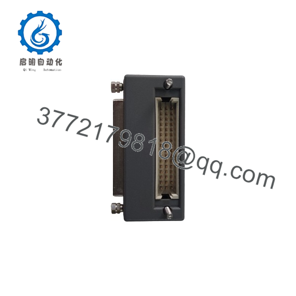
T9310-02
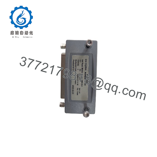
T9310-02
System Compatibility & Integration Requirements
| Item / Dependency | Verified Compatibility or Requirement | Practical Note |
| Processor Base Unit | T9100 Processor Base Unit | Connects directly to the left or right expansion port of the T9100 base unit. |
| I/O Base Units | T9300 3-Way I/O Base Unit | Plugs into the expansion bus ports of T9300 I/O base units across DIN rails. |
| System Bus Length Limit | 8 Meters Maximum Total Length | The combined length of all T9310 cable segments in a single system must not exceed 8 meters. |
| Termination Requirement | System Bus Termination Assemblies | Bus termination plugs must be installed on the unused end ports of the final base units in the chain. |
| Bending Radius | Minimum Static/Dynamic Bend Limits | Observe standard industrial cable bend radii when routing through cable trunking to avoid conductor stress. |
Dimensions, Mounting & Connection Notes
- Cable Length: 2.0 meters (6.56 feet) end-to-end.
- Connection Method: Multi-pin male/female latching connectors plug directly into dedicated bus expansion sockets on T9100 and T9300 base units.
- Routing Practice: Route the expansion cable through dedicated low-voltage signal trunking, physically separated from high-voltage AC power lines and motor leads.
- Mechanical Strain Relief: Utilize cabinet cable tie-downs near the base unit connection points to relieve mechanical stress on the interface sockets.
- Thermal Limit: Operating ambient temperature range of -25 °C to 70 °C (-13 °F to 158 °F).
FAQ
What is the primary function of the ICS Triplex T9310-02 cable?
The T9310-02 is a 2-meter I/O bus expansion cable used to connect an AADvance T9100 Processor Base Unit to T9300 I/O Base Units on adjacent DIN rails.
How long is the T9310-02 cable?
The T9310-02 cable assembly has a fixed length of 2.0 meters (6.56 feet).
What is the maximum total bus length allowed for an AADvance system?
The total combined length of all T9310 expansion cable segments connected in a single AADvance controller system must not exceed 8 meters (26.2 feet).
Does the T9310-02 cable support SIL 3 safety applications?
Yes, the cable is engineered with redundant internal conductors and heavy shielding, making it suitable for use in SIL 1 through SIL 3 safety systems.
Are bus terminators required when using the T9310-02 cable?
Yes, bus termination plugs must be fitted to the open expansion ports at the physical ends of the system bus chain to maintain signal reflection integrity.
Can the T9310-02 cable be cut or modified in the field?
No, the T9310-02 is a factory-sealed and tested cable assembly. Cutting or splicing the cable compromises EMC shielding, signal timing, and system safety certifications.
Verification & Troubleshooting Notes
- Latch Engagement: When installing, push connectors firmly into the base unit sockets until the mechanical latches click into place. A loose connection will trigger I/O bus communication fault alarms on the processor module.
- Bus Length Check: Verify that the total length of all expansion cables in the system chain does not exceed 8 meters; exceeding this limit can cause signal degradation and intermittent I/O card offline faults.
- Physical Cable Inspection: Check the cable jacket for outer sheath cuts or tight pinching against sharp enclosure edges that could compromise internal shield braid integrity.
- Termination Plugs: If I/O base units report bus communication failures, confirm that termination plugs are correctly seated in the final open sockets on the furthest base units.



