
 WhatsApp: +86 16626708626
 Email:
  Phone: +86 16626708626
Description
Key Technical Specifications
| Parameter | Specification |
|---|---|
| Manufacturer | ICS Triplex / Rockwell Automation |
| Model | T9432 |
| Product Family | Trusted / AADvance |
| Module Type | Analog Input |
| Number of Channels | 16 |
| Channel Isolation | Isolated analog inputs |
| Nominal Input | 4–20 mA DC |
| Maximum Input Range | 0–24 mA DC |
| Resolution | 0.98 μA, 15-bit |
| Sample Update Interval | 6 ms, no filter |
| Calibrated Accuracy at 25 °C | ±0.05 mA |
| Safety Accuracy Limit | ±200 μA |
| Module Supply | Redundant +24 VDC nominal |
| Supply Range | 18–32 VDC |
| Power Dissipation | 4.0 W |
| Channel Isolation Withstand | ±1.5 kVDC for 1 minute |
| Dimensions | 166 × 42 × 118 mm |
| Weight | 340 g |
Rockwell/ICS Triplex documentation identifies T9432 as the 16-channel version of the T9431/2 analog input family. The documentation specifies 0–24 mA maximum input range, 4–20 mA nominal operation, 15-bit resolution, 6 ms sample update time, and 4.0 W module power dissipation for T9432.
Product Introduction
The ICS Triplex T9432 is a 16-channel isolated analog input module for the Trusted/AADvance safety-control platform. It accepts industrial current-loop signals, with a nominal 4–20 mA range and a maximum specified measurement range of 0–24 mA. Each channel provides digitized analog data and diagnostic information to the system processor.
The T9432 is intended for safety-related process monitoring where channel isolation, diagnostics, and configurable input-line monitoring are important. The module supports multiple safety architectures, including 1oo1D, 1oo2D, and 2oo3D configurations. Rockwell’s documentation states that SIL 3 is the maximum achievable for a single channel; the actual safety integrity level depends on the complete system configuration.
Installation & Configuration Guide
Stage 1 — Pre-Installation Preparation (~5 minutes)
- Apply LOTO procedures and place the associated process in its approved maintenance state.
- Confirm the replacement is specifically T9432 and verify its hardware/software build.
- Record the existing module’s configuration and diagnostics.
- Photograph field wiring, terminal assemblies, module position, and status indicators.
- Back up the AADvance/Trusted application configuration.
- Use appropriate ESD protection before handling the module.
⚠️ Do not substitute T9431 for without checking the application. The two modules belong to the same family but provide different channel counts: T9431 has 8 inputs, while has 16.
Stage 2 — Removing the Existing Module (~5 minutes)
- Verify that the module is in the appropriate maintenance state.
- Confirm that removing it will not violate the configured safety architecture.
- Label field connections if the termination assembly is also being disturbed.
- Release the module’s mechanical retention.
- Withdraw the module carefully.
- Inspect the backplane and connector interfaces for contamination or mechanical damage.
Keep the removed module until commissioning has been completed and the replacement is proven.
Stage 3 — Installing the Replacement (~5 minutes)
- Confirm the catalog number and hardware revision.
- Check that the termination assembly and field wiring correspond to the intended installation.
- Use ESD precautions.
- Seat the squarely in the designated position.
- Secure the module using the manufacturer’s mounting procedure.
- Reconnect the field interface.
- Check polarity and loop wiring before applying power.
The ‘s analog-input line monitoring uses configurable measurement bands. The documented default thresholds are 0–3.8 mA for fault-low, 3.8–22.0 mA for normal operation, and greater than 22.0 mA for fault-high. These settings should be verified against the actual application configuration rather than assumed during commissioning.
Stage 4 — Power-On & Testing (~10–15 minutes)
- Restore redundant 24 VDC supply according to the approved procedure.
- Check module status and diagnostic indications.
- Verify that the controller recognizes the .
- Confirm all 16 channels are correctly configured.
- Inject or simulate known 4–20 mA signals where permitted.
- Compare displayed values against the calibrated test source.
- Check open-loop and over-range diagnostics.
- Verify configured line-monitoring thresholds.
- Confirm controller diagnostics and application status.
- Return the safety function to service only after the required acceptance checks are complete.
The documented resolution is 0.98 μA (15-bit), with a 6 ms sample update interval without filtering. These figures are useful when checking whether a replacement module is behaving consistently with the original installation.
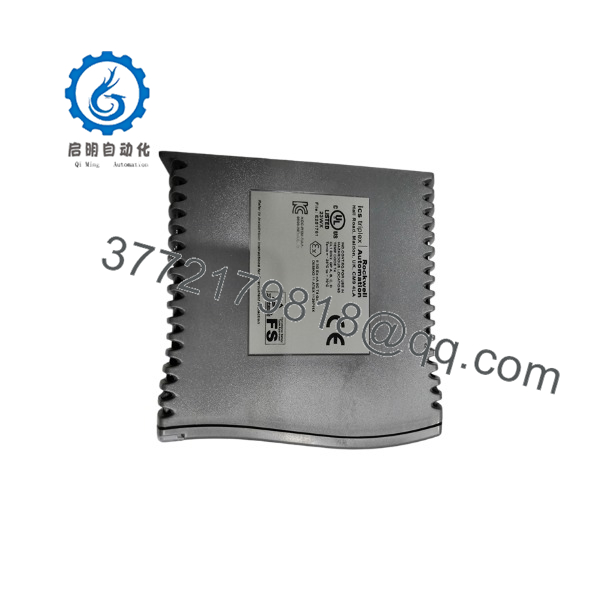
T9432
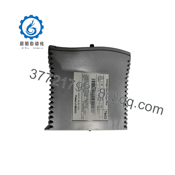
T9432
Frequently Asked Questions (FAQ)
Q1. What is the ICS Triplex ?
The is a 16-channel isolated analog input module in the ICS Triplex Trusted/AADvance product family. It is intended for acquisition and diagnostic monitoring of industrial analog signals, particularly 4–20 mA process instrumentation.
Q2. How many analog inputs does provide?
The provides 16 isolated analog input channels. This distinguishes it from the T9431, which provides eight channels.
Q3. Does support standard 4–20 mA transmitters?
Yes. Its nominal input range is 4–20 mA DC, with a maximum specified measurement range of 0–24 mA DC. This makes it suitable for conventional process transmitters when the field termination and system configuration are correctly matched.
Q4. What is the resolution?
The specified resolution is 0.98 μA, 15-bit. The documented sample update interval is 6 ms when no filtering is applied.
Q5. Is a TMR module?
The is designed for safety architectures including 1oo1D, 1oo2D, and 2oo3D. It should not be described simply as a three-channel analog input module. The safety architecture is established at the system/application level. Rockwell specifies SIL 3 as the maximum achievable for a single channel, subject to the selected system configuration.
Q6. Can be replaced while the system is running?
Do not assume unrestricted hot replacement. Whether online replacement is permissible depends on the specific Trusted/AADvance architecture, application configuration, redundancy arrangement, and approved maintenance procedure. A safety-system module should not be removed from an operating installation merely because the hardware is physically replaceable.
Q7. What should procurement verify before ordering ?
Verify the complete identification, hardware/software build, termination assembly, field wiring compatibility, condition, traceability, and test status. For a safety-system spare, the module’s revision and certification/configuration compatibility can matter as much as the base catalog number. Avoid treating third-party listings that call a “controller” or communications module as authoritative; the Rockwell documentation identifies as an analog input module.



