
 WhatsApp: +86 16626708626
 Email:
  Phone: +86 16626708626
Description
Key Technical Specifications
| Parameter | Specification Value |
| Part / Model Number | PF3S-PSA2 |
| Manufacturer | IDEC (IDEC Izumi) |
| System Compatibility | IDEC FA-3S / PF3S Series PLC Rack Systems |
| Input Voltage Range | Selectable 100–120 VAC / 200–240 VAC (50/60 Hz) |
| Output Voltage | 12 VDC nominal |
| Output Current Rating | 2.0 Amps (2000 mA) max |
| Mounting Style | Baseboard / Rack Slot Mount |
| Status Indicators | POWER LED (Green) |
| Protection Features | Internal Overcurrent Protection (OCP), Short Circuit Limiting |
| Weight | ~0.99 lbs (0.45 kg) |
Product Introduction
The IDEC PF3S-PSA2 is a modular system power supply unit designed specifically for the legacy IDEC FA-3S (PF3S) Programmable Logic Controller family. Mounted directly into the leftmost slot of an FA-3S rack or base unit, the module converts standard field AC line power (100–120V / 200–240V AC) into clean, regulated 12V DC power required by the CPU (such as PF3S-CP12), local bus, and connected digital/analog I/O expansion modules.
Equipped with built-in noise suppression, overcurrent protection, and power-line glitch filtering, the PF3S-PSA2 delivers steady current to sensitive PLC logic cards operating in demanding industrial environments. It is an essential, direct drop-in replacement part for maintenance teams sustaining mature IDEC automated production lines, packaging machinery, and material handling systems.
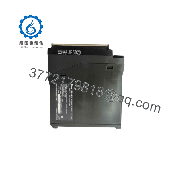
PF3S-PSA2
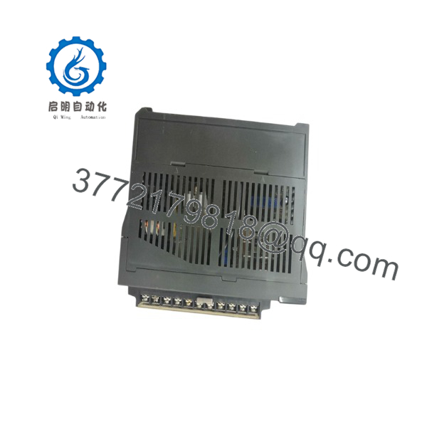
PF3S-PSA2
Troubleshooting Quick Reference
| Symptom | Possible Cause | Relevance to Part | Quick Check Method | Recommendation |
| POWER LED Off | No AC input voltage or blown internal line fuse | ✅ High | Measure AC voltage across input supply terminals using a DMM. | Verify external circuit breaker; replace internal supply module if AC voltage is present but LED remains off. |
| PLC CPU Resets Intermittently | DC voltage output dipping below threshold under load | ✅ High | Measure 12V DC bus voltage while the PLC system is actively executing logic and driving loads. | If 12V rail drops significantly under 2A load, replace the aging -PSA2 unit. |
| AC Line Fuse Blown On Power-Up | Internal primary stage short circuit or MOV failure | ✅ High | Check input terminals for low resistance / short circuit with power completely disconnected. | Do not bypass the fuse; replace the damaged power supply unit before re-energizing the rack. |
| I/O Bus Error / Rack Fault | Corrupted DC bus power or noise on backplane | ❓ Medium | Inspect system ground connection; check output rail ripple with an oscilloscope. | Ensure proper chassis grounding; replace power module if high AC ripple voltage is detected on DC bus. |
Frequently Asked Questions (FAQ)
Q: Is the IDEC -PSA2 still actively manufactured?
A: No, the / FA-3S series has been discontinued by the OEM (IDEC). However, high-quality New Surplus and fully tested Refurbished units remain readily available as direct replacements.
Q: What is the main DC output voltage of the -PSA2?
A: The module outputs a regulated 12V DC at up to 2.0 Amps (2000 mA) to power the CPU and backplane modules.
Q: Do I need to manually switch the input voltage between 110V and 220V AC?
A: Yes, verify the input selector terminal setup or internal voltage settings on the side panel before applying AC mains power to prevent damage.
Q: Can I hot-swap power supply while the PLC is running?
A: No. Always shut off the main AC line power and ensure the system is de-energized before removing or installing power modules into the PLC rack.
SOP Quality Control Process
- Visual & Structural Inspection: Check for housing cracks, terminal strip thread integrity, backplane pin condition, and factory label readability.
- AC Input Voltage Range Test: Verify power unit boot-up across both 100–120VAC and 200–240VAC ranges using an AC variac supply.
- Full-Load DC Output Test: Connect the 12V output rail to an electronic load bank set to 2.0A (2000 mA) for 4+ hours; verify voltage stability stays within \pm 2\%.
- Ripple & Noise Measurement: Check DC output with an oscilloscope under full load to ensure low peak-to-peak ripple noise.
- Anti-Static ESD Packaging: Clean module exterior and pack securely in static-shielding bags with custom foam protection prior to shipment.
Technical Pitfall & Survival Guide
- ❗ Total Load Over-Consumption: has a maximum rated output of 2.0A (2000 mA). If adding additional expansion I/O cards or high-draw sensors, calculate total rack current consumption to avoid overloading the unit.
- ❗ Incorrect AC Input Wiring: Applying 240VAC line power while configured for 120VAC will cause immediate catastrophic failure of the primary input bridge and capacitor stage. Double-check voltage settings prior to initial power-up.
- ❗ Chassis Grounding: Always ensure the frame ground (FG) terminal on the module is securely connected to a solid industrial ground point to prevent electro-static noise from coupling onto the PLC system bus.



