
 WhatsApp: +86 16626708626
 Email:
  Phone: +86 16626708626
Description
Key Technical Specifications
- Model: FZ1200R12KF1
- Manufacturer: Infineon Technologies (formerly EUPEC)
- Module Type: Single Switch IGBT Module
- Technology: IGBT Power Semiconductor Module
- Collector-Emitter Voltage (VCES): 1,200 V
- Continuous Collector Current (IC): 1,200 A
- Configuration: Single IGBT switch
- Housing Type: IHM / high-power module package
- Gate-Emitter Voltage (VGE): ±20 V maximum
- Isolation Voltage: 4 kV AC, 1 minute
- Internal Insulation Material: Al₂O₃ ceramic
- Baseplate Material: Copper
- Operating Temperature Range: Depends on application cooling design and datasheet conditions
- Storage Temperature: −40 to +150 °C
- Typical Applications: Industrial inverters, motor drives, power converters, renewable energy converters
The FZ1200R12KF1 belongs to Infineon’s 1,200 V / 1,200 A high-current IGBT module family. Related Infineon FZ1200R12 variants use a single-switch configuration with 140 mm × 130 mm class IHM packaging and are designed for industrial power conversion applications.
Product Introduction
The Infineon FZ1200R12KF1 is a high-current single-switch IGBT power module designed for industrial power electronics applications requiring high voltage blocking capability and large current handling. It is commonly used in inverter systems, motor drives, and high-power conversion equipment.
This module is selected for applications where thermal design, switching performance, and long-term electrical stability are critical. Before replacement, engineers should verify gate driver compatibility, mechanical dimensions, cooling design, and electrical ratings against the original module specification.
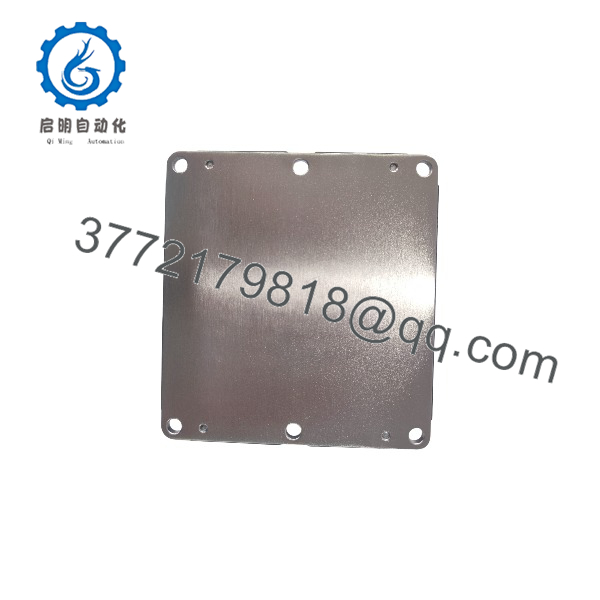
FZ1200R12KF1
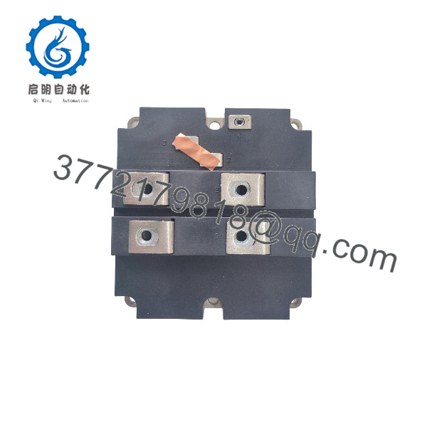
FZ1200R12KF1
Installation & Configuration Guide
Stage 1: Pre-Installation Preparation (Approx. 15 minutes)
⚠️ Safety First:
High-power IGBT modules can retain dangerous DC bus voltage after shutdown.
Before replacement:
- Disconnect the main power source.
- Apply lockout/tagout procedures.
- Confirm DC link voltage is discharged.
- Verify voltage with a properly rated multimeter.
- Wait according to the inverter manufacturer’s discharge procedure.
Tools Required:
- ESD wrist strap
- Insulated screwdriver set
- Digital multimeter
- Torque wrench
- Thermal interface material (if required)
- Smartphone for installation photos
Data Backup:
Before removing the existing module:
- Record the original IGBT part number.
- Photograph terminal connections.
- Document gate driver wiring.
- Record cooling interface condition.
- Check DC bus voltage and current ratings.
Stage 2: Removing the Old Module (Approx. 20 minutes)
Steps:
- Verify the DC bus voltage is fully discharged.
- Disconnect gate terminals carefully.
- Remove power terminals according to manufacturer torque requirements.
- Remove mounting screws evenly.
- Lift the module vertically from the heatsink.
⚠️ Note:
Do not pry the module from the heatsink. Excessive mechanical force can damage the ceramic insulation layer or terminal structure.
Stage 3: Installing the New Module (Approx. 30 minutes)
Steps:
- Inspect the heatsink surface.
- Remove old thermal compound completely.
- Apply the correct thermal interface material.
- Install the FZ1200R12KF1 in the correct orientation.
- Tighten mounting screws using a calibrated torque wrench.
- Reconnect power and gate terminals.
Configuration Verification (Critical):
- Confirm gate driver voltage matches the IGBT requirements.
- Verify gate resistor values.
- Check turn-on and turn-off protection settings.
- Confirm snubber and protection circuits are compatible.
- Verify current sensor calibration after replacement.
Self-Checklist:
- Module part number verified
- Thermal interface inspected
- Mounting torque completed
- Gate wiring checked
- Power terminals secured
Stage 4: Power-On & Testing (Approx. 30 minutes)
Pre-Power Check:
- Measure insulation resistance if required.
- Check for collector-emitter short circuit.
- Verify gate-emitter resistance.
- Confirm correct polarity.
Power-On Steps:
- Energize control power only.
- Verify gate driver status.
- Check fault monitoring circuits.
- Apply DC bus voltage gradually.
- Perform low-load operation test.
- Monitor temperature rise.
- Verify switching waveform if required.
⚠️ Troubleshooting Note:
- Immediate overcurrent faults may indicate incorrect gate drive settings.
- Excessive temperature rise may indicate poor thermal contact.
- Repeated IGBT failure often points to gate driver faults, snubber problems, or insufficient cooling rather than the module itself.
Frequently Asked Questions (FAQ)
Q1: Is the Infineon FZ1200R12KF1 still available?
Availability depends on distributor inventory and surplus stock channels. Some FZ1200R12 family modules remain available, while production status differs between specific suffix versions. Confirm current stock condition before purchase.
Q2: Can I replace FZ1200R12KF1 with another 1200 V 1200 A IGBT module?
Not automatically. Even modules with identical voltage and current ratings can have different electrical characteristics, mechanical dimensions, gate requirements, and switching behavior. Verify:
- Pin layout
- Gate threshold characteristics
- Switching losses
- Thermal resistance
- Driver compatibility
Q3: What applications use the ?
Typical applications include:
- Industrial motor drives
- High-power frequency converters
- UPS systems
- Renewable energy power conversion equipment
- Large industrial inverter platforms
Related FZ1200R12 family modules are specified for high-power converters, motor drives, and wind turbine applications.
Q4: What should I check before installing a replacement IGBT?
Do not only compare the part number. Check:
- DC bus voltage
- Load current
- Switching frequency
- Gate driver voltage
- Cooling capacity
- Protection circuit settings
A replacement module can fail quickly if the surrounding power stage is not compatible.
Q5: Why is this IGBT module expensive compared with standard semiconductor parts?
A 1,200 A IGBT module is a high-power component used in industrial energy conversion systems. The price reflects semiconductor die size, ceramic insulation structure, thermal requirements, and limited replacement inventory.
Q6: Is the supplied as new original or refurbished?
The condition must be confirmed by the supplier. New Original / New Surplus units should have original markings and packaging history. Refurbished modules should include electrical testing records, including insulation and switching checks.
Q7: What is the most common installation mistake with large IGBT modules?
A common failure point is incorrect thermal installation. Poor heatsink contact creates excessive junction temperature, causing premature failure. Always clean the mounting surface, apply the correct thermal interface material, and tighten mounting screws evenly to specification.



