
 WhatsApp: +86 16626708626
 Email:
  Phone: +86 16626708626
Description
Key Technical Specifications
| Parameter | Value |
|---|---|
| Manufacturer | Intelligent Motion Systems (IMS) |
| Model | IM483-PLG |
| Product Type | High performance microstepping driver |
| Motor Type | 2-phase stepper motor |
| Input Voltage | +12 to +48 VDC |
| Output Current | 0.4 to 4 A peak per phase |
| Maximum Step Frequency | 10 MHz |
| Input Signals | Step Clock, Direction, Enable, Reset |
| Connector Type | Altech 8-position pluggable interface |
| Microstep Resolution | Multiple selectable resolutions |
| Operating Temperature | 0 °C to +70 °C |
| Cooling Method | Heat sink / panel mounting dependent |
| Mounting | PCB or panel mounting configuration |
| Weight | Approximately 0.4 lb (0.18 kg) |
The IM483-PLG replaces the standard P1 and P2 connectors with an Altech 8-position pluggable interface. The design allows easier removal and replacement in machine-control assemblies.
Product Introduction
The Intelligent Motion Systems IM483-PLG is a high-performance microstepping driver designed for controlling two-phase stepper motors in industrial motion applications. It accepts a 12–48 VDC supply and provides up to 4 A peak phase current with Step Clock, Direction, Enable, and Reset inputs.
The PLG version uses a removable plug-in terminal interface instead of fixed connectors, making replacement easier in production equipment. Engineers commonly encounter this unit in legacy positioning systems, automation fixtures, semiconductor equipment, and precision motion assemblies.
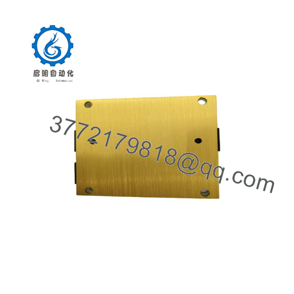
IM483-PLG
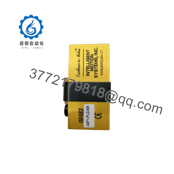
IM483-PLG
Installation & Configuration Guide
Stage 1: Pre-Installation Preparation — 5–10 minutes
⚠️ Safety First
- Notify production personnel of the planned downtime.
- Place the machine into a safe maintenance condition.
- Apply lockout/tagout procedures to the motor power supply.
- Verify the 12–48 VDC supply is removed before handling the driver.
- Wait for stored energy to discharge before removing wiring.
Tools Required
- ESD wrist strap
- PH1 screwdriver
- Digital multimeter
- Wire labels
- Smartphone for wiring photographs
- Small torque screwdriver
Data Backup
- Photograph the existing IM483 wiring.
- Record motor phase connections.
- Document Step, Direction, Enable, and Reset signal wiring.
- Record DIP switch settings.
- Record microstep resolution settings.
- Confirm motor current requirements from the machine documentation.
⚠️ Do not replace the IM483 based only on the model prefix. Confirm the connector style, current setting, motor type, and control wiring before installation.
Stage 2: Removing the Old Module — 5 minutes
- Remove the enclosure cover if required.
- Verify power is removed with a multimeter.
- Label every terminal before disconnecting.
- Remove the plug-in terminal blocks.
- Release the mounting hardware.
- Remove the driver carefully.
- Inspect the mounting surface and wiring for overheating or damage.
⚠️ Keep the original unit until the replacement passes testing. The old driver provides the best reference for switch settings and wiring.
Stage 3: Installing the New Module — 10 minutes
- Wear an ESD wrist strap before handling the board.
- Verify the replacement label reads IM483-PLG.
- Confirm voltage and current settings match the motor requirements.
- Transfer all switch settings from the original unit.
Configuration Clone (Critical)
- Match microstep resolution settings.
- Match current limit settings.
- Match Step/Direction signal configuration.
- Verify Enable and Reset polarity.
- Mount the driver securely.
- Install the plug-in terminal connectors.
- Confirm motor phase wiring before power-up.
Self-Checklist
- Correct model verified
- Supply voltage verified
- Current setting verified
- Motor phases checked
- Step/Direction wiring checked
- Terminal blocks locked
Stage 4: Power-On & Testing — 10–15 minutes
- Perform a final wiring inspection.
- Measure the DC supply voltage before connection.
- Power the driver without enabling motion.
- Verify status indicators.
- Send low-frequency Step commands.
- Confirm motor direction.
- Check for excessive heating or vibration.
- Increase operating speed gradually.
⚠️ Troubleshooting Note
- Motor does not move: Check Step signal polarity and Enable input.
- Motor moves incorrectly: Check Direction signal or motor phase wiring.
- Driver overheats: Verify current setting and motor specifications.
- Lost steps: Check acceleration profile and power supply capacity.
Frequently Asked Questions (FAQ)
Can I hot-swap the IMS IM483-PLG?
No. The -PLG is not designed for live replacement. Remove DC power before disconnecting terminals. Handling the driver while energized can damage the electronics and create a safety hazard.
the still manufactured?
The family is considered a legacy product. Current availability is generally limited to remaining stock, tested surplus units, or repair channels. Verify condition carefully because “available” does not always mean factory-new inventory.
What is the differenceeen and other versions?
The main difference is the connector arrangemThe replaces the normal P1 and P2 connectors with an Altech 8-position pluggable interface. Other versions such as -34P1 and -8P2 use different connection methods.
Can I re an with an IM804/IM805-PLG?
The connector interface is pin-compatible, but that does not automatically make it a direct electrical replacement. Verify motor current requirements, supply voltage, configuration settings, and machine control requirements before substitution.
Will I lose machine settings when replathe ?
The does not store machine PLC logic. However, the driver’s hardware settings, including current and microstep configuration, must be transferred manually. Always photograph the original settings before removal.
Why is the price lower than buying a new motion controller?
Legacy industrial parts are often sourced from surplus inventory, machine decommissioning, or repair stock. Pricing depends on condition: New Original/New Surplus units, tested refurbished units, and used parts have different value levels. Confirm the supplied condition before purchase.
What information should I provide when ord an ?
Provide:
- Full modeler:
- Photos of the existing label
- Supply voltage
- Motor model and phase current
- Existing wiring photos
- Application type
This prevents receiving a physically similar driver with incorrect electrical settings.



