
 WhatsApp: +86 16626708626
 Email:
  Phone: +86 16626708626
Description
Key Technical Specifications
| Parameter | Value |
|---|---|
| Manufacturer | Jaquet Technology / TE Connectivity |
| Model | DSF 1410.00 AHV |
| Product Number | 374Z-03940 |
| Product Family | DSF xx10.xx AxV |
| Product Type | Single-channel Hall effect speed sensor |
| Sensing Principle | Magnetically biased Hall effect semiconductor |
| Primary Function | Generates square-wave pulses proportional to rotational speed |
| Target Requirement | Ferromagnetic pole wheel |
| Output Type | Short-circuit-proof push-pull output stage |
| Supply Voltage | 10–30 V DC |
| Maximum AC Ripple on Supply | 25 mV peak-to-peak |
| Reverse-Polarity Protection | Yes |
| Current Consumption | Maximum 14 mA without load |
| Minimum Operating Frequency | 0.05 Hz |
| Sensor Axis Sensitivity | Independent of rotational orientation of sensor axis |
| Thread | M14 × 1 |
| Connection Style | Integral connector |
| Connector Part Number | Jaquet 820A-35731 |
| Operating Temperature | −40 to +125 °C |
| Approximate Sensor Weight | 90 g |
| Certification | Germanischer Lloyd approval reported for DSF sensor family |
| Housing / Ingress Protection | Confirm from the exact product drawing and installed connector assembly |
| Output Logic / Pinout | Verify from the original wiring drawing and 374Z-03940 product documentation before connection |
TE Connectivity / Jaquet identifies the DSF 1410.00 AHV, Product Number 374Z-03940, as a single-channel Hall effect speed sensor in the DSF xx10.xx AxV family. The sensor works with a pole wheel to generate speed-proportional square-wave signals and uses a magnetically biased Hall element with a short-circuit-proof push-pull output. The official data sheet lists 10–30 V DC supply, 0.05 Hz minimum frequency, M14 × 1 thread, integral connector, −40 to +125 °C operation, and 90 g weight.
Product Introduction
The Jaquet DSF 1410.00 AHV, Part Number 374Z-03940, is a single-channel Hall effect speed sensor for monitoring rotational speed from a ferromagnetic pole wheel. It converts passing gear teeth or pole-wheel segments into a square-wave output signal for turbine controls, diesel engines, marine propulsion equipment, pumps, compressors, generators, and industrial rotating machinery.
This is an active 10–30 V DC sensor with a push-pull output, not a passive variable-reluctance pickup. Match the exact part number, M14 × 1 mechanical thread, connector type, pole-wheel geometry, installed air gap, supply voltage, controller input type, and cable wiring before replacement. A sensor that physically threads in can still produce unusable speed feedback if those details do not match.
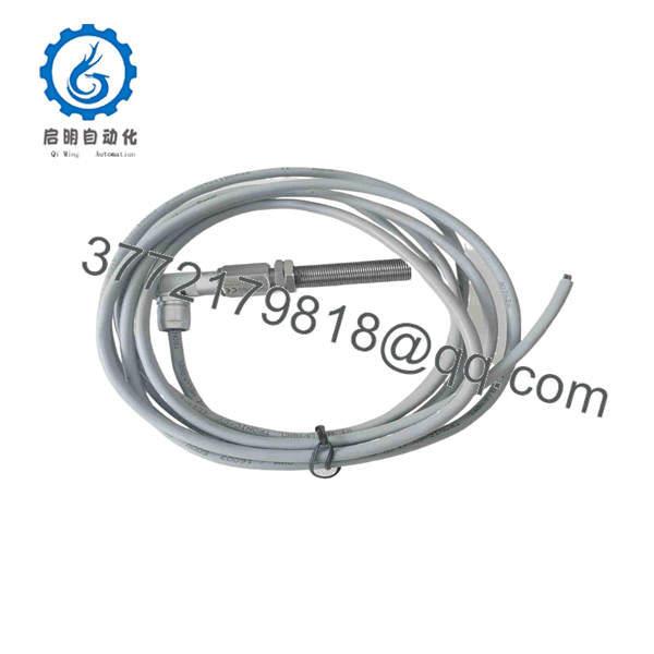
DSF 1410.00 AHV
Troubleshooting Quick Reference
| Symptom | Possible Cause | Relevance to This Part | Quick Check Method | Recommendation |
|---|---|---|---|---|
| No speed signal at controller | Missing DC supply, incorrect polarity, broken cable, failed sensor, excessive air gap, damaged pole wheel | ✅ High | Measure supply voltage at the sensor connector with the sensor connected. Confirm 10–30 V DC and correct polarity. Then check output activity while the shaft turns slowly. | Repair supply or cabling first. If supply is correct but output remains fixed with a verified target, replace the sensor. |
| Sensor output is permanently high or low | Open output wire, short to supply or 0 V, damaged push-pull stage, no ferromagnetic target, incorrect input pull-up configuration | ✅ Medium | Disconnect from the controller only under approved procedure. Measure output relative to supply and 0 V while rotating the pole wheel. Compare with a known-good sensor. | Verify wiring and controller input design. If output does not switch at the sensor under a valid target condition, the sensor may be defective. |
| Speed reading is unstable or drops out | Excessive air gap, tooth damage, eccentric pole wheel, loose sensor, cable shielding issue, electrical noise, connector contamination | ⚠️ Medium | Inspect sensor mounting and target wheel. Check for damaged or missing teeth. Scope the output waveform while rotating and compare amplitude, duty cycle, and noise with a healthy channel. | Correct mechanical alignment and cable routing before replacing the sensor. |
| Sensor works at low speed but fails at operating speed | Vibration, cable intermittency, target runout, noise pickup, controller input bandwidth issue | ⚠️ Medium | Check the waveform at the sensor and controller input while increasing speed. Inspect mounting torque, cable strain relief, and proximity to VFD or ignition wiring. | Improve mounting, shielding, grounding, and cable routing. Replace the sensor only if the fault remains at the sensor output. |
| No signal after a sensor replacement | Wrong pinout, incorrect connector, wrong supply polarity, sensor installed too far from target, incompatible push-pull versus passive input | ✅ High | Compare original and replacement labels, connector pinout, cable colors, thread depth, and air gap. Verify controller input is designed for an active Hall-effect output. | Do not wire from memory. Confirm the 374Z-03940 connection diagram and controller interface before powering up. |
| Signal frequency is correct but indicated RPM is wrong | Incorrect pulses-per-revolution setting, wrong pole-wheel tooth count, controller scaling error, missed pulses | ❌ Usually low | Count pole-wheel teeth or poles and compare the controller scaling to RPM=60fNRPM = \frac{60f}{N}, where ff is frequency in Hz and NN is pulses per revolution. | Correct the controller scaling or target-wheel data. The sensor does not determine pulses per revolution by itself. |
| Output signal contains noise spikes | Poor shield termination, cable routed with motor leads, damaged connector seal, ground loop, power-supply ripple | ⚠️ Medium | Inspect cable routing and shield bonding. Measure supply ripple; the data sheet permits only 25 mV peak-to-peak AC ripple. Use an isolated oscilloscope for waveform checks. | Improve supply filtering, shielding, and routing. Keep sensor cable away from motor and contactor conductors. |
| Sensor heats up or fails repeatedly | Incorrect voltage, reverse wiring, shorted output, unsuitable hazardous-area or temperature rating, mechanical damage | ✅ High | Verify 10–30 V DC supply and wiring before connecting a replacement. Check ambient temperature at the mounting point and inspect for target contact damage. | Correct root cause before replacement. Do not use the non-Ex AHV sensor in a hazardous area unless the approved system documentation permits it. |
| Speed signal disappears only when equipment is hot | Cable insulation degradation, connector expansion, sensor thermal issue, target runout at temperature | ⚠️ Medium | Trend supply and output waveform during warm-up. Inspect connector retention and cable condition near hot machinery. | Test the sensor at temperature and inspect the cable route. The specified ambient range is −40 to +125 °C, but installation conditions still matter. |
| Signal works at sensor but not at controller | Open cable conductor, failed terminal, wrong controller input configuration, poor shield/ground reference | ❌ Low | Compare waveform at the sensor connector and controller input terminal. Perform continuity checks with power isolated. | Repair cable or controller input wiring before replacing the sensor. |
❗ Installation warning: Do not set the sensor air gap by feel. Use the machine OEM’s specified gap and installation method. A DSF sensor can produce a clean signal at hand-turning speed yet drop pulses at operating speed because of target runout, vibration, or an air gap set too close to the limit.
❗ Wiring warning: This is an active Hall effect sensor with a push-pull output. It is not wired or tested like a two-wire magnetic pickup. Verify supply, 0 V, and output pins from the correct connector drawing before connection. Do not apply a megger to the sensor electronics.
If troubleshooting stalls, provide technical support with photos of the full sensor label, Product Number 374Z-03940, connector and cable, pole-wheel tooth count, measured supply voltage, sensor air gap, controller input type, and an output waveform captured at both the sensor and controller.
Frequently Asked Questions
What is the Jaquet DSF 1410.00 AHV?
The DSF 1410.00 AHV is a Jaquet Technology / TE Connectivity single-channel Hall effect speed sensor. It works with a ferromagnetic pole wheel and produces a square-wave output signal proportional to rotational speed.
What is the part number for DSF 1410.00 AHV?
The standard DSF 1410.00 AHV is listed as Product Number 374Z-03940. Verify this number on the actual sensor label because related DSF 1410 variants may have different connector, cable, insertion-length, hazardous-area, or output characteristics.
What voltage does DSF 1410.00 AHV require?
The data sheet lists a 10–30 V DC supply range, reverse-polarity protection, and a maximum permitted superimposed AC ripple of 25 mV peak-to-peak. Current consumption is listed as a maximum of 14 mA without load.
Is DSF 1410.00 AHV a passive magnetic pickup?
No. It is an active Hall effect speed sensor with a magnetically biased Hall semiconductor and a short-circuit-proof push-pull output stage. It requires DC supply power and provides a switching output, unlike a passive variable-reluctance pickup that generates an AC voltage without an external supply.
What is the minimum speed DSF 1410.00 AHV can detect?
The DSF sensor family is specified to generate pulses down to a frequency of 0.05 Hz. Actual lowest usable shaft speed depends on the pole-wheel tooth count. For example, with a 60-tooth wheel, 0.05 Hz0.05\ Hz corresponds to 0.05 pulses per second, or approximately 0.05 RPM. With a 30-tooth wheel, it corresponds to approximately 0.1 RPM.
What thread and connector does DSF 1410.00 AHV use?
The standard model has an M14 × 1 thread and an integral connector. The data sheet lists Jaquet connector Part Number 820A-35731 for DSF 1410.00 AHV. Confirm the mating connector, cable pinout, and insertion depth before ordering because nearby DSF variants use other cable and connector arrangements.
Is DSF 1410.00 AHV approved for hazardous areas?
Do not assume so. The base DSF 1410.00 AHV listed here is distinct from specially marked Ex-ATEX DSF variants. Use only the exact hazardous-area-certified sensor and installation method specified by the site’s area classification and equipment documentation.
Can I replace DSF 1410.00 AHV with DSF 1410.03 AHV?
Not without a full comparison. Both are part of the DSF family, but suffixes can change dimensions, connector style, insertion length, mechanical drawing, electrical configuration, approvals, or target requirements. Match the complete model and Product Number, not just “DSF 1410.”
Why is a New Surplus DSF 1410.00 AHV cheaper than an OEM channel?
New Surplus sensors may come from unused marine, turbine, generator, or industrial-maintenance inventory. Lower price can reflect inventory age or a missing mating connector rather than sensor condition. Request photos of the exact label, Part Number 374Z-03940, connector face, thread condition, storage packaging, warranty terms, and return policy.
What testing should a supplier perform before shipping a used or refurbished sensor?
Request visual inspection for thread damage, connector corrosion, cracked housing, and cable damage; label verification; controlled 10–30 V DC power-up; output switching test against a suitable ferromagnetic target; frequency verification at a known target speed; current-consumption check; and a written test record. A bench test does not replace final adjustment to the installed pole wheel, air gap, cable run, controller input, and machine operating environment.



