
 WhatsApp: +86 16626708626
 Email:
  Phone: +86 16626708626
Description
Key Technical Specifications
| Parameter | Value |
|---|---|
| Manufacturer | KEBA |
| Model Number | DO321 |
| Product Family | KEBA I/O Modules |
| Module Type | Digital Output Module |
| Signal Type | Digital switching outputs |
| Output Voltage | 24 V DC |
| Output Channels | Configuration dependent on hardware version |
| Application | Machine control, robotics, industrial automation |
| System Integration | KEBA KeControl automation platforms |
| Installation | KEBA controller/I/O expansion system |
| Typical Loads | Relays, solenoid valves, contactors, actuators |
| Communication | Internal KEBA I/O bus interface |
| Mounting | Industrial control cabinet installation |
Product Introduction & Supply Chain Strategy
KEBA DO321 is a digital output module used in KEBA automation systems to control external field devices through 24 V DC switching signals. It is commonly installed in machine tools, robotics systems, packaging equipment, and industrial production equipment requiring reliable distributed I/O control.
For factories operating KEBA-based machines, maintaining DO321 as New Original / New Surplus inventory provides a practical lifecycle protection strategy. Controlled spare holding reduces production downtime risk, avoids emergency sourcing costs, and supports lower Total Cost of Ownership (TCO) compared with premature machine control replacement.
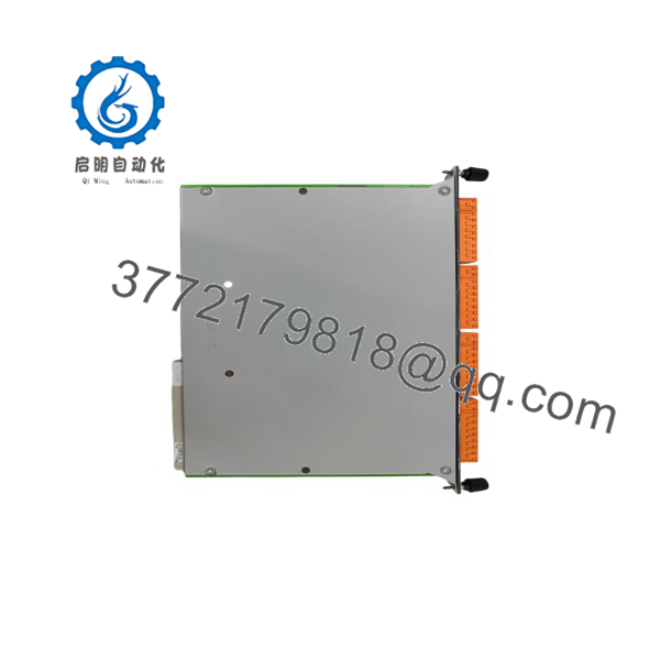
DO321
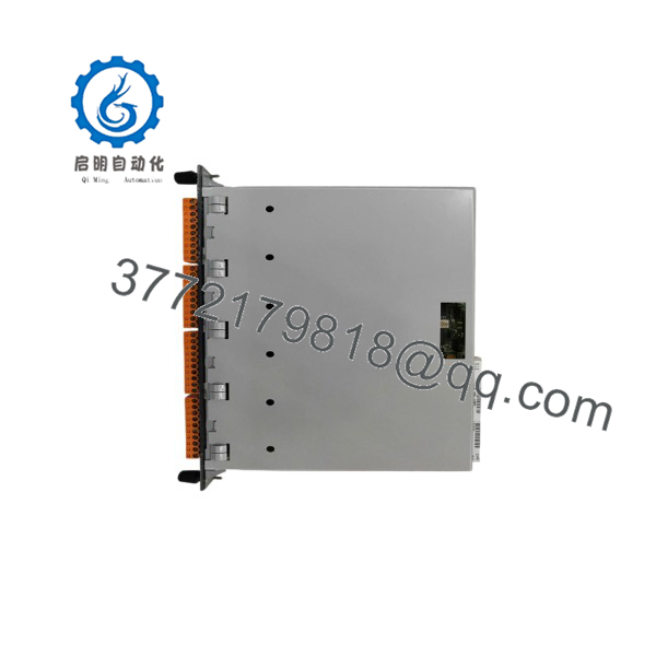
DO321
Installation & Configuration Guide
Stage 1: Pre-Installation (Prep & Safety)
- Perform machine lock-out/tag-out before accessing the control cabinet.
- Disconnect control and field power supplies.
- Verify the 24 V DC supply is isolated.
- Wear a grounded ESD wrist strap before handling the DO321 module.
- Record existing configuration details:
- Module position
- Hardware revision
- I/O mapping
- Terminal wiring
- Controller software version
- Take clear photos of:
- Terminal connections
- Module arrangement
- Status indicators
- Address settings if applicable
Required tools:
- ESD wrist strap
- Digital multimeter
- Insulated screwdriver
- KEBA engineering software
Stage 2: Removal
- Confirm the machine is in a safe maintenance state.
- Disconnect field wiring carefully.
- Release the module locking mechanism.
- Remove the DO321 module from the I/O assembly.
- Inspect connectors and mounting points.
Avoid bending connector pins or applying excessive force during removal. Mechanical damage can create intermittent communication faults.
Stage 3: Installation (Clone & Seat)
- Verify replacement compatibility:
- KEBA DO321 model
- Hardware revision
- Controller platform compatibility
- Install the module into the original position.
- Confirm the module is fully seated.
- Reconnect wiring according to the recorded documentation.
- Verify each output channel matches the original I/O assignment.
Do not change output allocation during a direct replacement unless the machine software is updated and validated.
Stage 4: Power-On & Testing
- Measure 24 V DC supply voltage before power restoration.
- Check output circuits for shorts.
- Restore cabinet power.
- Observe module diagnostic indicators.
- Verify controller communication.
- Test output channels:
- Valve activation
- Relay switching
- Actuator movement
- Machine sequence operation
- Confirm the machine completes normal operating cycles before production release.
Firmware/Software Versions & Upgrade Notes
- Recommended Firmware: Match the hardware revision and KEBA controller software configuration already installed on the machine.
- Configuration Requirement: Confirm the replacement module exists correctly in the KEBA project configuration before commissioning.
- Compatibility Check: Verify controller firmware, I/O bus version, and module revision compatibility.
- Upgrade Warning: Avoid controller software upgrades during a hardware replacement unless required. Firmware changes may require complete machine validation.
- Backup Requirement: Save the original KEBA project file, I/O mapping, and machine parameters before replacement.
Recommended documentation:
- Controller firmware version
- KEBA project backup
- I/O address allocation
- Module hardware revision
- Machine safety configuration
Frequently Asked Questions (FAQ)
Q1: Is the KEBA supplied as a new module?
Yes. The supplied KEBA is a Brand New Surplus unit. It is not pulled from retired equipment and not refurbished. Each module is checked for authenticity, storage condition, connector integrity, and shipment protection.
Q2: Why is New Surplus KEBA pricing different from OEM purchasing?
New Surplus inventory comes from global industrial stock sources. It provides a supply option for legacy KEBA systems where standard purchasing channels may have limited availability.
Q3: Why keep a spare in inventory?
A failed output module can stop machine sequences by disabling connected field devices. Maintaining 1–2 units as buffer stock helps maintenance teams restore operation faster.
Q4: Can the KEBA be replaced while the machine is running?
Do not assume live replacement is allowed. Follow KEBA system documentation and plant safety procedures before removing any active I/O module.
Q5: Will replacing require machine programming?
The hardware replacement normally requires configuration verification rather than complete machine reprogramming. Always restore and verify the original KEBA project before commissioning.
Q6: What checks are performed before shipment?
Quality checks include model verification, serial identification review, visual inspection, connector inspection, ESD-safe handling, and protective packaging.
Q7: How should KEBA spare inventory be managed?
Use equipment criticality, failure history, and lead time variability to establish Min/Max stock levels. For production-critical machines, maintain buffer stock and evaluate Last-time-buy opportunities before supply becomes restricted.



