
 WhatsApp: +86 16626708626
 Email:
  Phone: +86 16626708626
Description
Key Technical Specifications
| Parameter | Value |
|---|---|
| Manufacturer | Keysight Technologies / Agilent Technologies |
| Model | E1421B |
| Product Type | VXI mainframe |
| VXI Size | C-size |
| Number of Slots | 6 |
| VXI Compliance | VXIbus Specification Revision 1.4 |
| Backplane | VXI P1/P2 connectors |
| Usable Power | 450 W maximum at 55 °C |
| +5 V Output | 45 A peak |
| +12 V Output | 8 A peak |
| −12 V Output | 8 A peak |
| +24 V Output | 8 A peak |
| −24 V Output | 8 A peak |
| −5.2 V Output | 40 A peak |
| −2 V Output | 15 A peak |
| AC Input | 100–240 VAC ±10%, 50–60 Hz ±10% |
| 400 Hz Input | 100–120 VAC ±10% |
| DC Input | 100–370 VDC |
| Maximum Inrush Current | 40 A |
| Cooling | Pressurized air-channel system |
| Airflow | Intake from right side; exhaust from left |
| Dimensions | Approximately 221.5 × 425.5 × 558.8 mm without bottom feet |
| Weight | Approximately 13.9 kg |
| Operating Temperature | 0 °C to 55 °C |
| Non-operating Temperature | −40 °C to +75 °C |
| Acoustic Noise | Approximately 53 dBA low-speed / 59 dBA high-speed fan |
The E1421B’s six C-size slots, 450 W maximum usable power, VXIbus Revision 1.4 compatibility, and power-output ratings are documented in the available Keysight/Agilent technical material.
The mainframe accepts A- or B-size VXI modules when used with the optional E1403 module carrier. Its power input is located at the rear, while cooling air enters from the right and exhausts through the left.
Product Introduction
The Keysight E1421B is a C-size, six-slot VXI mainframe for assembling automated test and measurement systems around VXI instrumentation. It provides the VXI backplane, system power, mechanical support, and forced-air cooling required by compatible VXI modules. Keysight specifies compliance with VXIbus Revision 1.4.
Its compact six-slot format suits smaller VXI installations where a full 13-slot E1401B mainframe is unnecessary. The power supply provides up to 450 W of usable power at 55 °C, with rear-access power-supply serviceability and right-to-left airflow through the chassis.
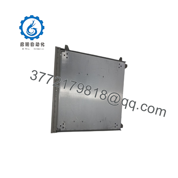
E1421B
Installation & Configuration Guide
Stage 1: Pre-Installation Preparation — 10 minutes
⚠️ Safety First: Shut down the VXI system and disconnect the AC input before installing, removing, or servicing the E1421B. The mainframe contains a high-power supply and can present hazardous voltages even after shutdown. Follow the documented discharge and service procedures.
Tools Required:
- ESD wrist strap
- Appropriate screwdriver set
- Digital multimeter
- Rack hardware, if rack mounting
- VXI module documentation
- Smartphone or camera for installation records
System Checks:
- Verify that the incoming supply is compatible with the E1421B input range.
- Confirm adequate rack or bench clearance.
- Keep the right-side air intake unobstructed.
- Keep the left-side exhaust path unobstructed.
- Calculate the combined power requirement of the installed VXI modules.
- Confirm the total module load remains within the mainframe’s available power.
⚠️ Do not evaluate capacity from the +5 V rating alone. VXI modules can draw from multiple backplane supply rails.
Stage 2: Removing the Existing Mainframe — 15–20 minutes
- Stop all automated test activity.
- Place the connected VXI system in a safe state.
- Switch the mainframe to standby/off.
- Disconnect the AC input.
- Remove external controller, interface, and instrumentation connections.
- Label cables before removal.
- Remove rack hardware or mounting accessories.
- Support the approximately 13.9 kg chassis during removal.
- Slide the mainframe out without twisting the chassis.
- Inspect the rack surface and surrounding ventilation space.
⚠️ Do not lift the unit by connectors, front-panel controls, or removable power-supply components.
Stage 3: Installing the E1421B — 15–20 minutes
- Verify the replacement model is .
- Inspect the chassis for shipping damage.
- Confirm the six C-size VXI slots are unobstructed.
- Position the chassis so the right-side intake and left-side exhaust have sufficient clearance.
- Install the required rack flange, handle, or slide hardware.
- Secure the chassis mechanically.
- Connect the AC input using the appropriate line cord.
- Connect the VXI controller/interface.
- Install VXI modules according to their individual installation procedures.
- Confirm each module is properly seated before applying power.
The uses VXI P1/P2 backplane connectors and incorporates automatic VMEbus grant and interrupt-acknowledge daisy-chain jumpering, eliminating manual switch selection for those backplane functions.
Self-Checklist:
- Six-slot C-size chassis verified
- Rack hardware secured
- Right-side intake unobstructed
- Left-side exhaust unobstructed
- AC input verified
- VXI modules correctly seated
- Controller/interface connected
- Total power demand calculated
Stage 4: Power-On & Testing — 10–15 minutes
- Verify all installed modules are correctly seated.
- Confirm the mainframe is connected to the correct AC source.
- Switch the mainframe on.
- Check the front-panel power indication.
- Confirm the cooling fans operate normally.
- Check for abnormal fan noise or vibration.
- Verify the VXI controller recognizes the installed system.
- Check the VXIbus communication path.
- Initialize each installed instrument individually.
- Run a known-good automated test sequence.
- Monitor the mainframe for abnormal heating during the initial operating period.
⚠️ Cooling is not optional. The uses forced airflow through the chassis. Blocking the right-side intake or left-side exhaust can alter module temperature and affect system reliability. Keysight specifies a pressurized air-channel cooling arrangement for the mainframe.
Frequently Asked Questions (FAQ)
How many VXI modules can the hold?
The provides six C-size VXI slots. It can also accommodate A- or B-size modules when the appropriate E1403 module carrier is used.
Is the still manufactured by Keysight?
No. Keysight currently lists the as obsolete. Its product page identifies the 34980A Multifunction Switch/Measure Unit as a replacement product, but that does not mean the 34980A is a mechanical drop-in replacement for the chassis.
What is the maximum usable power of the ?
Keysight documentation specifies 450 W maximum usable power at 55 °C. Individual backplane rails also have separate current limits, so system loading must be checked rail by rail when the installed modules have significant power requirements.
What input voltage does the accept?
For 50–60 Hz operation, the specified nominal input range is 100–240 VAC ±10% with automatic voltage ranging. The documentation also specifies a 100–120 VAC ±10% range for 400 Hz operation and 100–370 VDC for DC input.
Does the contain the VXI controller?
No. The is a mainframe, not the system controller. It provides the chassis, backplane, power, cooling, and mechanical infrastructure for VXI modules. A separate VXI controller or external interface is required depending on the system architecture. Keysight’s VXI installation documentation shows used with controllers and interfaces such as E1406A, E8491A, and E1482B.
Can I replace an with a used unit?
Yes, provided the replacement passes a proper inspection and electrical test. Because the is obsolete, used and surplus units are the practical procurement route. Check the power supply, fans, backplane connectors, slot mechanics, line-input configuration, and insulation condition before installing it into a production ATE system.
What should I check before buying a surplus ?
Request photographs of the front, rear, internal power-supply area if available, and all six slot connectors. Confirm the serial number and condition of the chassis. For a production system, I would also want evidence that the power supply starts correctly, the cooling fans operate at both expected speeds, and the backplane does not show damaged or contaminated connectors.
The is a legacy VXI chassis, so condition matters more than cosmetic appearance. A clean front panel does not prove that the power supply and cooling system are healthy.



