
 WhatsApp: +86 16626708626
 Email:
  Phone: +86 16626708626
Description
Key Technical Specifications
| Parameter | Value |
|---|---|
| Manufacturer | KLA-Tencor |
| OEM Part Number | 0037183-004 |
| Product Type | MMD Measurement Head Board |
| Board Category | Measurement / Optical Measurement PCB |
| Equipment Family | KLA-Tencor AIT systems |
| Measurement Function | MMD measurement |
| Assembly Type | Electronic PCB assembly |
| System Application | Semiconductor inspection / metrology |
| Related Assembly | MMD measurement head |
| Known Equipment Association | AIT / AIT Fusion UV systems |
| Hardware Revision | -004 |
| Input/Output Specification | Verify against the target AIT system documentation |
| Supply Voltage | Verify from the applicable KLA-Tencor equipment schematic |
| Communication Interface | System-dependent; verify before replacement |
| Operating Temperature | Verify against the host equipment specification |
| Condition Availability | Tested used / surplus inventory varies by supplier |
Available industrial equipment records identify 0037183-004 as a KLA-Tencor MMD Measurement Head Board used on KLA-Tencor AIT systems. ClassOne Equipment lists the same OEM part number and identifies the component as an MMD Measurement Head Board.
Additional semiconductor-equipment inventory records associate 0037183-004 with KLA-Tencor AIT Fusion UV equipment and describe related assemblies as polarization and MMD measurement components.
Important procurement note: Public sources do not provide enough authoritative information to state the board’s exact supply voltage, connector pinout, electrical tolerances, or communication protocol. Those values should not be guessed from reseller listings. Verify them against the equipment-specific KLA-Tencor documentation before installation.
Product Introduction
KLA-Tencor 0037183-004 is an MMD Measurement Head Board associated with KLA-Tencor AIT semiconductor inspection equipment. Supplier records specifically identify the OEM part number and its use in AIT systems.
This is a system-specific measurement PCB rather than a general-purpose automation I/O module. Replacement should therefore be based on the exact OEM part number, board revision, host AIT platform, and installed optical measurement configuration.
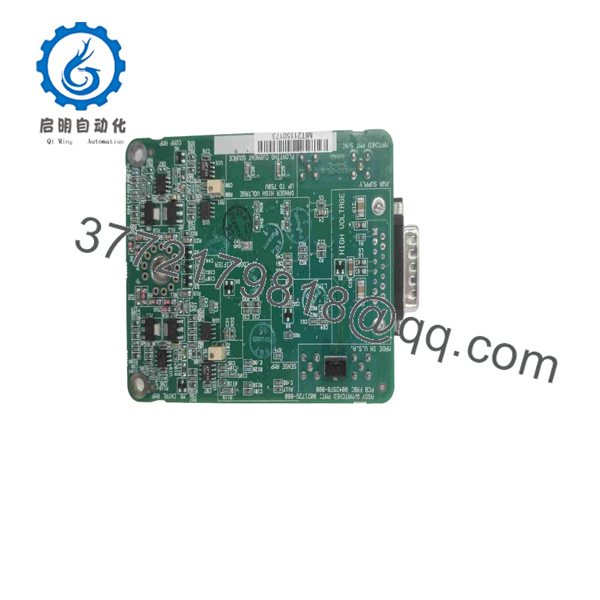
0037183-004
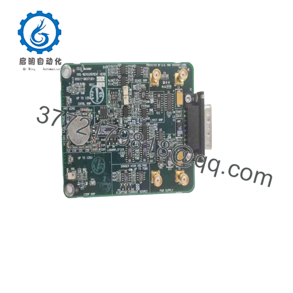
0037183-004
Installation & Configuration Guide
Stage 1: Pre-Installation Preparation — Approximately 15 Minutes
⚠️ Safety First: Put the AIT system into its approved maintenance state, stop wafer processing, follow the equipment-specific shutdown procedure, isolate applicable power sources, and follow the site’s lockout/tagout requirements.
Tools Required:
- ESD wrist strap
- Appropriate Phillips/flat-head screwdrivers
- Digital multimeter
- Connector labels
- Smartphone or camera
- Equipment-specific service documentation
Data Backup / Documentation:
- Record the complete 0037183-004 part number.
- Photograph the board before removal.
- Record PCB revision markings and serial number.
- Photograph every connector and cable position.
- Record any jumper, switch, or configuration settings.
- Document the host AIT system model and software revision.
- Preserve the removed board until the replacement has passed system calibration.
⚠️ Do not treat this board as a generic PCB replacement. MMD measurement hardware is tied to the optical and measurement architecture of the host system.
Stage 2: Removing the Old Board — Approximately 10 Minutes
- Complete the manufacturer’s shutdown sequence.
- Verify that the applicable electrical supplies are isolated.
- Use an ESD wrist strap before opening the electronics area.
- Photograph all connectors before disconnecting them.
- Label cables according to their original positions.
- Release the board retention hardware.
- Disconnect connectors without pulling on cable conductors.
- Remove the PCB straight from its guide or mounting position.
- Inspect the connector contacts and mating hardware.
- Check for contamination, corrosion, damaged pins, or mechanical damage.
⚠️ Keep the original 0037183-004 available as a reference. Do not discard it until the replacement has completed functional verification.
Stage 3: Installing the New Board — Approximately 10 Minutes
- Verify that the replacement is marked 0037183-004.
- Compare PCB revision and physical layout with the removed board.
- Confirm connector locations match.
- Check that no foreign material is present around the board connector.
- Install the PCB into the correct guides or mounting position.
- Seat the board evenly without forcing it.
- Secure the retaining hardware.
- Reconnect each cable according to the photographs.
- Verify connector locking mechanisms.
- Perform a final visual inspection before restoring power.
Self-Checklist:
- 0037183-004 verified
- PCB revision documented
- Correct AIT system confirmed
- ESD precautions maintained
- Connectors correctly identified
- Board fully seated
- Retaining hardware secured
- No loose cables or foreign material
Stage 4: Power-On & Testing — Approximately 15–30 Minutes
- Restore system power according to the approved AIT startup procedure.
- Observe the equipment startup sequence.
- Check for board-related hardware alarms.
- Verify that the measurement subsystem recognizes the replacement board.
- Check system diagnostics.
- Confirm communication between the measurement head electronics and the controller.
- Run the equipment’s prescribed measurement-head diagnostic.
- Perform the applicable optical or measurement calibration.
- Compare diagnostic readings with the pre-replacement baseline.
- Run a controlled qualification test before returning the equipment to production.
⚠️ Do not release the system to production solely because the board powers up. A measurement PCB can pass basic hardware initialization while still producing incorrect measurement data.
⚠️ If the system reports a measurement-head or calibration fault, first verify connector seating, board revision, host-system compatibility, and configuration before assuming the replacement PCB is defective.
Frequently Asked Questions (FAQ)
What is KLA-Tencor 0037183-004?
It is an MMD Measurement Head Board used in KLA-Tencor AIT equipment. ClassOne Equipment specifically identifies 0037183-004 as an MMD Measurement Head Board and associates it with KLA-Tencor AIT systems.
What does MMD mean on this part?
The available equipment records identify the assembly as an MMD Measurement Head component, but public sources do not provide enough authoritative documentation to expand the acronym with confidence for every AIT platform. For technical documentation, it is safer to retain the OEM designation MMD Measurement Head Board rather than invent an expansion.
Is 0037183-004 a PLC or general-purpose I/O module?
No. It is identified as a measurement-head PCB for KLA-Tencor semiconductor inspection equipment. It should not be evaluated like a conventional PLC CPU, analog input card, or industrial communication module.
Can I replace 0037183-004 with another MMD board?
Do not assume interchangeability. The -004 revision is part of the OEM identification. Verify the complete part number, PCB revision, host AIT model, and measurement configuration before installing another board.
Is 0037183-004 obsolete?
It is associated with legacy KLA-Tencor AIT equipment and is primarily encountered through specialized semiconductor-equipment spare-parts suppliers and used-equipment inventories. Current supplier records show tested and used examples, but stock condition varies.
What condition should I specify when purchasing it?
Specify the condition explicitly: New Original / New Surplus / Tested Used / Refurbished. For a measurement board, ask for actual board photographs, the OEM label, PCB revision, serial number, test status, and warranty terms.
Why should I provide the AIT system model before ordering?
Because 0037183-004 is a system-specific measurement board, and public listings do not establish complete electrical and software compatibility across every AIT configuration. Providing the host equipment model allows the supplier to check the correct board revision instead of matching the part number alone.



