
 WhatsApp: +86 16626708626
 Email:
  Phone: +86 16626708626
Description
Key Technical Specifications
| Parameter | Value |
|---|---|
| Manufacturer | Kollmorgen / Seidel |
| Model | 60WKS-CE240/22PB |
| Series | 60WKS |
| Product Type | Analog Servo Amplifier |
| Input Supply | 3-phase, 60–172 V AC |
| Input Frequency | 50/60 Hz |
| DC Link Voltage | 240 V DC |
| Peak Output Current | 60 A |
| Peak Duration | 5 seconds |
| Output Stage | 3-phase, 4-quadrant |
| Control Functions | PI / current / speed |
| Logic Voltage | 24 V |
| Control Isolation | Optocoupler-isolated |
| Setpoint Inputs | 2 differential inputs |
| Tacho Input | DC, brushless, or 3-phase tachometer |
| Rotor Feedback | RLG rotor-position sensor |
| Enable Input | Yes |
| Expansion Slot | Optional PCB-01 |
| Ballast Circuit | 5.4 kW peak / 135 W continuous |
| Cooling | Natural convection |
| Protection Class | IP44 |
| Approx. Weight | 1.4 kg |
| Lifecycle | Legacy / discontinued |
The available technical documentation and industrial listings agree on the major electrical architecture: three-phase input, 240 V DC link, 3-phase 4-quadrant output stage, PI/current/speed control, 24 V isolated logic, and multiple feedback options.
Identification warning: Some secondary-market listings describe the part inconsistently, including references to a worm-gear reducer or servo motor. The more technically detailed listing identifies 60WKS-CE240/22PB as an analog servo amplifier, which is the classification used here.
Product Introduction
The Kollmorgen 60WKS-CE240/22PB is a legacy three-phase analog servo amplifier from the 60WKS series. It uses a 240 V DC link and a 3-phase 4-quadrant output stage for closed-loop servo motor control. The control section provides PI, current, and speed regulation with two differential setpoint inputs.
The amplifier accepts DC, brushless, or three-phase tachometer feedback and an RLG rotor-position signal. Its 24 V logic interface uses isolated optocouplers, and an expansion slot accommodates an optional PCB for functions such as ramp generation and limit-switch logic.
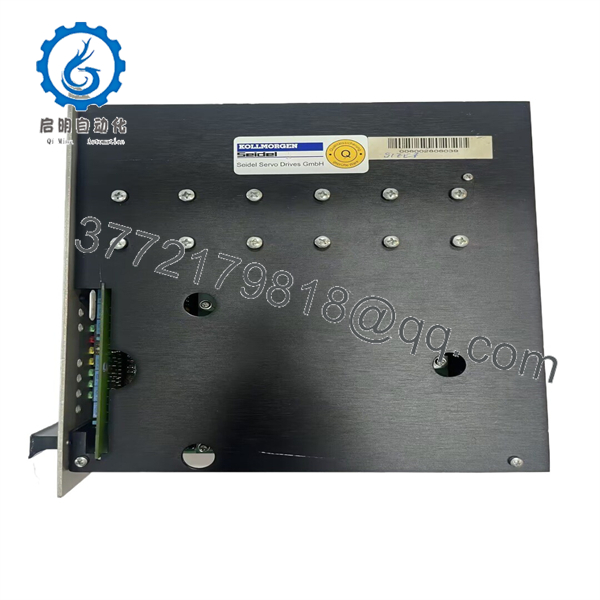
60WKS-CE240/22PB
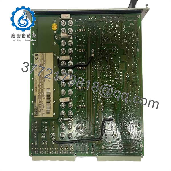
60WKS-CE240/22PB
Installation & Configuration Guide
Stage 1: Pre-Installation Preparation
Estimated time: 20–30 minutes
⚠️ Safety First: This drive operates with hazardous AC and DC-link voltages. Isolate the incoming three-phase supply, apply LOTO, and verify the DC bus has discharged before touching terminals.
Tools Required:
- ESD wrist strap
- CAT-rated digital multimeter
- Insulated screwdrivers
- Wire labels
- Smartphone/camera
- Existing drive documentation
- Motor nameplate data
Data Backup:
- Record the complete 60WKS-CE240/22PB designation.
- Photograph every terminal connection.
- Photograph all PCB adjustment potentiometers and switches.
- Record motor model and rated current.
- Document tachometer and RLG feedback wiring.
- Record setpoint and enable connections.
- Photograph any optional PCB installed in the expansion slot.
⚠️ Do not rely on wire color alone. On legacy servo installations, feedback wiring and control references can vary considerably between machine builders.
Stage 2: Removing the Old Amplifier
Estimated time: 15–25 minutes
- Open the upstream disconnect and apply LOTO.
- Verify the AC input is de-energized.
- Measure the DC bus and confirm it has fallen to a safe voltage.
- Record the existing terminal assignments.
- Label motor U/V/W connections.
- Label tachometer and RLG feedback wiring.
- Label enable, setpoint, limit-switch, and auxiliary connections.
- Disconnect wiring without pulling on individual conductors.
- Remove mounting hardware.
- Remove the amplifier and inspect the mounting area.
⚠️ Never assume the DC bus is discharged because the input contactor is open. Measure it.
Stage 3: Installing the Replacement
Estimated time: 20–30 minutes
- Verify the replacement model: 60WKS-CE240/22PB.
- Compare the terminal layout with the original unit.
- Inspect connectors and terminal screws.
- Verify the correct motor voltage/current configuration.
- Confirm feedback type matches the existing motor.
- Mount the amplifier securely.
- Reconnect three-phase input wiring.
- Reconnect motor output wiring.
- Reconnect tachometer/RLG feedback.
- Reconnect enable and setpoint signals.
- Verify ballast/braking connections where applicable.
- Check all terminals before energizing.
Self-Checklist:
- Model verified
- AC input wiring checked
- Motor U/V/W checked
- DC bus/braking circuit checked
- Tachometer wiring checked
- RLG feedback checked
- Enable input checked
- Setpoint wiring checked
- Mounting secured
Stage 4: Power-On & Testing
Estimated time: 30–60 minutes
- Keep the motor mechanically safe and uncoupled where practical.
- Energize the control supply.
- Verify the 24 V logic supply.
- Confirm no fault indication is present.
- Apply main power under controlled conditions.
- Verify the DC-link voltage.
- Confirm feedback signals.
- Apply a low-level speed/current command.
- Verify correct motor rotation.
- Check current feedback.
- Increase command gradually.
- Verify acceleration and deceleration.
- Test the enable and limit-switch circuits.
- Monitor amplifier temperature.
- Perform a controlled load test.
⚠️ Wrong feedback wiring can cause an immediate uncontrolled motion condition. Keep the first rotation test at low command and with the machine mechanically secured.
Frequently Asked Questions (FAQ)
What is Kollmorgen 60WKS-CE240/22PB?
It is a 60WKS-series analog servo amplifier designed for closed-loop control of compatible servo motors. It uses a three-phase supply, 240 V DC link, and 3-phase 4-quadrant output stage.
What is the DC bus voltage?
The specified DC-link voltage is 240 V DC. The listed three-phase input range is approximately 60–172 V AC at 50/60 Hz.
What is the peak output current?
The available technical listing specifies 60 A peak output current for up to 5 seconds. Do not interpret this as a continuous 60 A rating.
What feedback devices can it accept?
The 60WKS amplifier architecture supports DC, brushless, and three-phase tachometer inputs, together with an RLG rotor-position sensor input. Confirm the feedback type of the installed motor before ordering a replacement.
Does it support four-quadrant operation?
Yes. The output stage is specified as a 3-phase 4-quadrant output stage, making the amplifier applicable to applications requiring motoring and regenerative operation.
Is the 60WKS-/22PB obsolete?
It is a legacy Kollmorgen/Seidel product and is primarily encountered through secondary-market inventory. Current suppliers list new-surplus and used/refurbished units rather than presenting it as a current-generation Kollmorgen drive.
Can I substitute another 60WKS model?
Not simply because it belongs to the same series. Variants such as 60WKS-/12PB and 60WKS-/26PB have different configuration designations. Verify motor current, feedback, control configuration, braking requirements, and machine-specific adjustments before substitution.
What should procurement verify?
Request the complete designation 60WKS-/22PB, plus photographs of the nameplate and terminal/PCB configuration. For surplus equipment, also verify whether the unit is New Original/New Surplus or Refurbished, whether it has been function-tested, and whether the original adjustment settings have been documented.



