WhatsApp: +86 16626708626
 Email:
 Phone: +86 16626708626
Description
Core Product Summary
The Kollmorgen S70602-PBNANA is a fully digital servo amplifier from the S700 series, built on the 6 Arms current frame of the dual-channel-STO hardware generation. The order code decodes precisely: S7 identifies the S700 family, 06 the 6 Arms current rating, 0 the 208–480 V supply version, 2 the standard electrical/mechanical configuration with dual-channel STO hardware, and -PBNANA the expansion configuration — a PROFIBUS DP card in slot 1 with no additional cards in slots 2 and 3, leaving EtherCAT and CANopen onboard.
The drive connects to a grounded three-phase supply from 3×208 V to 3×480 V (±10%, 50/60 Hz), draws 4.5 kVA rated input power, and delivers 6 Arms continuous, 18 Arms peak for approximately 2 seconds, or 12 Arms for approximately 5 seconds, at an 8 kHz output stage switching frequency. The integrated Safe Stop supports up to SIL CL 3 per IEC 62061 and PLe per ISO 13849-1, with two STO Enable inputs. Feedback evaluation covers resolver, encoder, AquadB, and ComCoder signals, and the integrated position controller closes position on the drive itself. Commissioning uses the DriveGUI setup software over RS-232, or two front-panel keys and the 3-character LED display. The 70 mm-wide housing weighs 4.4 kg and mounts vertically at IP20 with a built-on fan.
Key Technical Specifications
| Parameter | Value |
|---|---|
| Product family / type | S700 series digital servo amplifier (dual-channel STO hardware), 6 Arms frame, PROFIBUS DP expansion card in slot 1 |
| Supply input | 3×208 V to 3×480 VAC (grounded supply, phase to phase), ±10%, 50/60 Hz |
| Rated input power | 4.5 kVA |
| Maximum DC bus link voltage | 900 VDC; bus link can be paralleled between amplifiers |
| Rated output current | 6 Arms (±3%) |
| Peak output current | 18 Arms (approx. 2 s, ±3%); 12 Arms (approx. 5 s, ±3%) |
| Switching frequency of output stage | 8 kHz |
| Voltage rise speed (dU/dt) | 3.0 kV/µs at 3×208 V to 6.9 kV/µs at 3×480 V (measured without connected motor) |
| Minimum motor inductance | Supply-voltage dependent: approx. 1.2 mH at 3×208 V, 1.3 mH at 3×230 V, 2.2 mH at 3×400 V, 2.7 mH at 3×480 V |
| Output current form factor | 1.01 (rated conditions, minimum load inductance) |
| Current controller | Digital, space-vector PWM, 62.5 µs cycle, bandwidth > 1.2 kHz (up to 5 kHz) |
| Speed / position controller | Adjustable digital speed controller 62.5 µs; integrated position controller 250 µs (optionally 125 µs) |
| Residual voltage drop at rated current | 4 V |
| Fieldbus (this configuration) | PROFIBUS DP expansion card in slot 1; two 9-pin Sub-D sockets wired in parallel |
| Onboard interfaces | EtherCAT, CANopen, RS-232, 24 V step/direction interface |
| Feedback evaluation | Resolver, encoder, AquadB encoder, ComCoder |
| Functional safety | Safe Stop STO onboard, dual channel: up to SIL CL 3 per IEC 62061 and PLe per ISO 13849-1; two STO Enable inputs |
| Inputs / outputs | 2 programmable analog inputs (±10 V), 4 programmable digital inputs, 2 direction-selectable digital inputs/outputs, 1 Enable input, 2 STO Enable inputs, BTB/RTO relay output; separate 24 V supply input for digital outputs |
| Auxiliary supply | 24 VDC (−0/+15%), electrically isolated, internally fused; 1 A without brake, 3 A with brake; brake output 0.15 / 2 A |
| Programmability | Macro programming in IEC 61131 structured text; memory card slot for parameter records and firmware |
| Dimensions (H × W × D without connectors) | 345 mm × 70 mm × 243 mm (379 mm × 70 mm × 285 mm with connectors) |
| Weight | 4.4 kg |
| Enclosure protection | IP20 (IEC 60529) |
| Ambient temperature | 0 to +40 °C at rated data; +40 to +55 °C with 2.5 %/°C power derating |
| Humidity / altitude | Max. 85% relative humidity, no condensation; up to 1000 m unrestricted, 1000–2500 m with 1.5%/100 m derating |
| Mounting / cooling | Vertical mounting; built-on fan; sufficient forced ventilation in the cabinet required |
| Regen circuit | Internal brake resistor standard; external brake resistors optional; dynamic distribution of regenerative power between amplifiers on a common DC bus link |
Engineering Selection Highlights
- PROFIBUS DP card in slot 1 defines the control architecture — the drive is commanded as a PROFIBUS DP slave with two parallel-wired 9-pin Sub-D sockets; the controller side needs a DP master, and cable selection, shielding, and termination follow the PROFIBUS User Organization installation guidelines rather than drive-specific rules.
- Dual-channel STO up to SIL CL 3 / PLe — unlike the single-channel hardware (SIL CL 2 / PLd), this generation supports higher safety levels with two STO Enable inputs, allowing standards-based safe stop integration without external contactor hardware in suitable circuits; the function must still be tested at startup and after wiring changes.
- Two peak ratings, not one — 18 Arms is available for approximately 2 seconds and 12 Arms for approximately 5 seconds; check the acceleration cycle against both limits, because longer bursts fall to the lower figure.
- Supply-voltage-dependent motor matching — minimum motor inductance (1.2–2.7 mH) and motor-side dU/dt (3.0–6.9 kV/µs) both scale with the supply voltage; verify winding inductance and motor insulation against the actual mains before commissioning.
- Slots 2 and 3 remain open in this order code — NA/NA means no fan controller, PosI/O, or safety card is fitted; if the machine later needs the F2 controlled-fan option or a safety card, that is a different order code, and the F2 fan option cannot be retrofitted later.
- Onboard EtherCAT and CANopen remain available — even with the PROFIBUS card fitted, the onboard interfaces can be used for commissioning and parameter access, so the fieldbus choice does not block drive-level diagnostics.
- Tight thermal envelope — full rating applies to +40 °C ambient only, with 2.5 %/°C derating to +55 °C, and the built-on fan presupposes cabinet forced ventilation; budget for this in multi-axis panels.
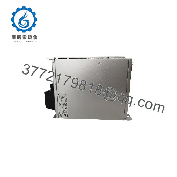
S70602-PBNANA
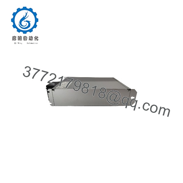
S70602-PBNANA
System Compatibility & Integration Requirements
| Item / Dependency | Verified Compatibility or Requirement | Practical Note |
|---|---|---|
| Motion network | PROFIBUS DP expansion card (slot 1), two 9-pin Sub-D sockets wired in parallel | Cable routing, bus connector, termination, and transmission times per the PROFIBUS User Organization installation guidelines; protocol functions per the manufacturer’s PROFIBUS DP communication profile documentation |
| Onboard communication | EtherCAT and CANopen onboard (slots 2 and 3 unoccupied in this order code) | Available for commissioning, diagnostics, or alternative machine architectures |
| Mains supply | Grounded 3×208 V to 3×480 VAC TN/TT network | Connection to other supply types only via isolating transformer; single-phase supply possible for setup |
| Auxiliary control power | External 24 VDC supply, −0/+15% | 1 A without motor brake, 3 A with brake; digital outputs use a separate 24 V input |
| Feedback devices | Resolver (max. 100 m), encoder (max. 50 m), AquadB, ComCoder (max. 25 m) | Cable types and cross-sections per the manual’s connection data; a motor choke (3YL/3YLN) is required for motor cables of 25–50 m |
| Motors | Synchronous servomotors; S700 platform also supports linear motors, asynchronous motors, and DC motors | Verify minimum inductance for the supply voltage used |
| Commissioning | DriveGUI setup software via RS-232, or two keys and the 3-character LED display | Fully programmable via RS-232; parameter records and firmware accessible via smartcard |
| Functional safety | STO dual channel, up to SIL CL 3 per IEC 62061 and PLe per ISO 13849-1 | Two STO Enable inputs; wiring examples in the instruction manual; function test required at initial startup and after any change |
| Safety expansion | Slot available for safety cards with additional safe-drive functions (e.g., safety card S1-2, SIL CL 3, or S2-2, SIL CL 2) | Described in separate documentation; not fitted in this order code |
| Regen energy | Internal brake resistor standard; external optional; DC bus link paralleling with dynamic regen distribution | Permitted between several amplifiers of the same series |
Dimensions, Mounting & Connection Notes
| Item | Data |
|---|---|
| Height × Width × Depth | 345 × 70 × 243 mm without connectors; 379 × 70 × 285 mm with connectors |
| Weight | 4.4 kg |
| Mounting | Vertical mounting position; built-on fan; keep ventilation unobstructed and provide forced ventilation in the control cabinet; the drive shuts down on overtemperature (motor loses torque) |
| Power connections | Power-Combicon connectors (X0, X8, X9); recommended tightening torque 0.7–0.8 Nm |
| Control connections | Mini-Combicon connectors X3A/B/C for control signals; X4A/B for auxiliary voltage |
| Feedback / serial connectors | Resolver via 9-pin Sub-D socket (X2); encoder via 15-pin Sub-D socket (X1); PC/CAN via 9-pin Sub-D plug (X6); encoder emulation ROD/SSI optional via 9-pin Sub-D plug (X5) |
| PROFIBUS connection | Two 9-pin Sub-D sockets wired in parallel on the expansion card; card supply voltage provided by the amplifier |
| Grounding | Grounding bolt, 3.5 Nm; all shielding connections made directly at the amplifier |
| External fusing (6 A frame) | AC supply feed 10 AT (10 A) time-delay; 24 V feed and brake resistor 10 AT; EU fuse types gRL or gL, US fuse classes RK5/CC/J/T time-delay |
| Conductor cross-sections (S701–S706) | AC connection and DC bus link 1.5 mm²; motor cable 1–1.5 mm²; brake resistor 1 mm² |
| Motor cable limits | Max. 25 m without choke; 25–50 m with a 3YL or 3YLN motor choke wired close to the amplifier |
| Environmental limits | 0 to +40 °C at rated data (2.5 %/°C derating to +55 °C); max. 85% RH non-condensing; up to 1000 m altitude unrestricted (1.5%/100 m to 2500 m); pollution level 2 per IEC 60664-1 |
Detailed Product Overview
The S700 dual-channel generation covers 1.5 A to 24 A frames in a 70 mm-wide housing (100 mm for the 24 A model), with current and voltage designations embedded in the order code. S70602-PBNANA reads as follows: 6 Arms rated current, 208–480 V supply version, standard electrical/mechanical configuration with dual-channel STO hardware, PROFIBUS DP expansion card in slot 1, and no expansion cards in slots 2 and 3 — the configuration that keeps EtherCAT and CANopen onboard as the default communication. This code precision matters in practice: an S70602-SENA-NA is the same power stage with a SERCOS card instead, and an S70602-NANANA has no expansion card at all. The fieldbus suffix must match the machine’s controller architecture, and because slots 2 and 3 in this code are empty, later additions such as the controlled-fan option F2 are order-code changes, not field retrofits.
Electrically, the drive spans the full industrial low-voltage range: 3×208 V to 3×480 V, ±10%, 50/60 Hz, connected directly to a grounded TN or TT network. The 6 Arms output stage delivers 18 Arms for about two seconds and 12 Arms for about five, giving machine builders two acceleration envelopes to design against — a distinction that matters on axes with longer ramps, where the five-second figure governs. The 8 kHz switching frequency, 1.01 output current form factor, and a current controller with more than 1.2 kHz bandwidth on a 62.5 µs cycle place the drive’s control performance on the same digital platform as the rest of the S700 generation: adjustable speed controller at 62.5 µs and an integrated position controller at 250 µs, optionally 125 µs.
Supply voltage interacts with motor selection in two documented ways. The minimum motor inductance rises from 1.2 mH on a 208 V network to 2.7 mH at 480 V, so a low-inductance winding acceptable at one site may fall outside limits after a supply change. And the motor-side voltage rise rate scales from 3.0 to 6.9 kV/µs across the same span, which drives insulation stress and EMC layout decisions; the manual requires a 3YL or 3YLN motor choke for cable lengths between 25 and 50 m and caps resolver, encoder, and ComCoder cable lengths at 100 m, 50 m, and 25 m respectively with specified cable types.
The PROFIBUS card integrates the drive into a DP network through two 9-pin Sub-D sockets wired in parallel. Its protocol functions follow the manufacturer’s PROFIBUS DP communication profile documentation, while cabling practice — bus connector, termination, shielding, transmission times — follows the PROFIBUS User Organization guidelines. In day-to-day operation this means the axis is parameterized and commanded from the DP master, with the onboard RS-232, CANopen, or EtherCAT available for commissioning and diagnostics independently of the fieldbus.
The defining feature of this hardware generation is the dual-channel Safe Stop, rated up to SIL CL 3 per IEC 62061 and PLe per ISO 13849-1, with two STO Enable inputs instead of the single-channel generation’s one. For machine builders, this provides a higher-integrity path to a standards-based safe stop within the drive itself, and the manual documents example circuits for both single-axis and multi-axis emergency-stop integration. The platform additionally reserves an expansion path for safety cards with further safe-drive functions for applications beyond STO. As with all STO implementations, the drive cannot hold suspended loads in the safe state, so vertical axes require mechanical blocking; and the safety function must be retested after any wiring or component change.
Installation follows the platform conventions: vertical mounting, 4.4 kg, 345 × 70 × 243 mm without connectors, IP20 enclosure, and a built-on fan that assumes forced ventilation in the cabinet. Full rating applies to +40 °C with 2.5 %/°C derating up to +55 °C, and altitude derating begins above 1000 m. External fusing for the 6 A frame is a 10 AT time-delay fuse on the AC feed. With macro programming in IEC 61131 structured text, a memory card slot for parameters and firmware, and logical combination options across the onboard I/O, the drive supports both simple point-to-point axes and coordinated machine sections under one PROFIBUS master.
Applications & System Role
In the machine architecture, the S70602-PBNANA operates as a networked single-axis servo amplifier in a PROFIBUS DP-controlled system: the DP master — typically a PLC motion controller — sends setpoints and receives status cyclically, while the drive closes its current, speed, and position loops locally and converts the commands into regulated motor current through an IGBT output stage at 8 kHz.
Fit scenarios that follow from the verified capability profile:
- Axes on PROFIBUS DP-based machines, common in European-style automation architectures, where one controller coordinates multiple drives over the fieldbus.
- Axes with 6 Arms continuous demand and bursts up to 18 Arms for short cycles or 12 Arms for longer ones — positioning, feed, and handling axes with moderate continuous torque.
- Safety-relevant machine designs that benefit from the dual-channel onboard Safe Stop rated up to SIL CL 3 / PLe, avoiding external contactor hardware in the drive power path in suitable circuits; suspended loads still require mechanical blocking.
- Applications using resolver, encoder, AquadB, or ComCoder feedback without additional interface hardware.
- Multi-axis cabinets where several S700 drives share a common DC bus link and distribute regenerative braking energy dynamically.
The engineering boundaries are the +40 °C full-rating ambient, the supply-voltage-dependent minimum motor inductance and dU/dt, the motor cable length limits without a choke, and the requirement for a grounded TN/TT supply network.
FAQ
What is the Kollmorgen S70602-PBNANA?
It is an S700-series digital servo amplifier in the 6 Arms frame, dual-channel-STO hardware generation, fitted with the PROFIBUS DP expansion card in slot 1 and no additional cards in slots 2 and 3.
What does the order code mean?
S7 is the S700 family, 06 the 6 Arms current rating, 0 the 208–480 V supply version, 2 the standard dual-channel-STO configuration, and -PBNANA the PROFIBUS card in slot 1 with unoccupied slots 2 and 3 (EtherCAT and CANopen onboard).
What are its current and power ratings?
Rated output current is 6 Arms (±3%), with 18 Arms peak for approximately 2 seconds and 12 Arms for approximately 5 seconds; rated input power is 4.5 kVA.
What supply does it need?
A grounded three-phase supply from 3×208 V to 3×480 VAC (±10%, 50/60 Hz), TN or TT network with grounded neutral; other supply types require an isolating transformer.
How does the PROFIBUS interface connect?
Through the PROFIBUS DP expansion card, which has two 9-pin Sub-D sockets wired in parallel; cabling and termination follow the PROFIBUS User Organization installation guidelines.
What safety function is built in?
A dual-channel Safe Stop (STO) rated up to SIL CL 3 per IEC 62061 and PLe per ISO 13849-1, with two STO Enable inputs; it must be function-tested at initial startup and after any wiring or component change.
Which feedback devices does it support?
Resolver, encoder, AquadB, and ComCoder signals are evaluated onboard, with maximum cable lengths of 100 m (resolver), 50 m (encoder), and 25 m (ComCoder) using the specified cable types.
How is the drive commissioned?
With the DriveGUI setup software over the RS-232 interface, or with two front-panel keys and the 3-character LED display; parameters and firmware can also be accessed via the memory card slot.
What installation limits apply?
Vertical mounting at IP20 with built-on fan, 0 to +40 °C at rated data (2.5 %/°C derating to +55 °C), up to 1000 m altitude unrestricted, and maximum 85% relative humidity without condensation.