WhatsApp: +86 16626708626
 Email:
 Phone: +86 16626708626
Description
Key Technical Specifications
| Parameter | Specification / Value |
| Model Number | KSD1-48 |
| Part Number | 00-108-301 / 00-112-259 |
| Compatible Controller | KUKA KRC2 / KRC2 Ed05 Cabinet |
| Peak Output Current | 48 A |
| Rated Output Current | 24 A RMS |
| DC Bus Input Voltage | 600 V DC |
| Control Supply Input | 24 V DC (±10%) |
| Communication Interface | Interbus Fiber Optic Cable (FO) |
| Feedback Interface | Resolver Input / EnDat Absolute Encoder |
| Cooling Method | Forced air via rear heatsink / internal cabinet airflow |
| Operating Temperature | 0 to +55 °C (+32 to +131 °F) |
| Weight | 8.5 kg (18.7 lbs) |
Product Introduction & Supply Chain Strategy
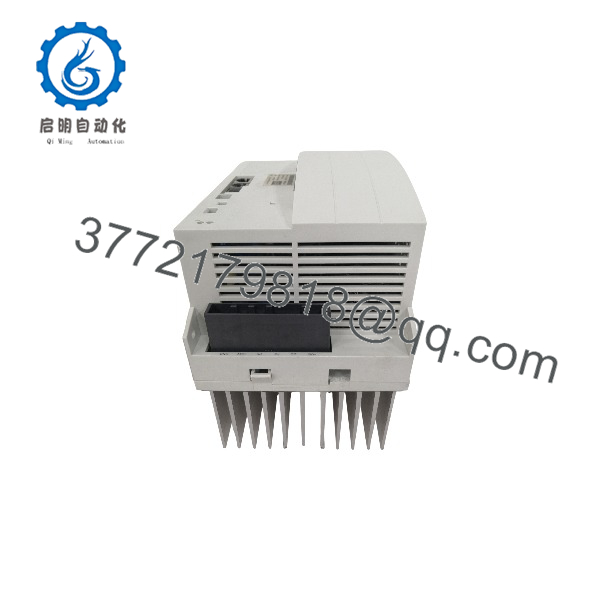
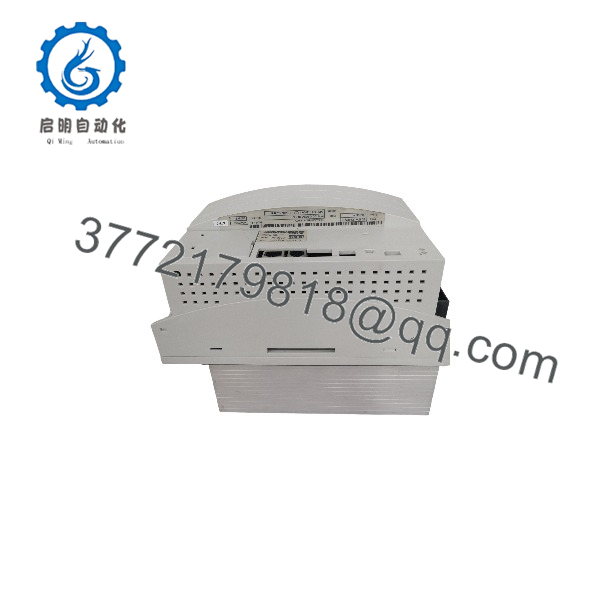
The KUKA KSD1-48 is a 48-amp single-axis servo drive module engineered for the KRC2 robot controller family. It converts the 600V DC bus voltage into precise 3-phase AC power to drive high-load axis motors (typically Axes 1, 2, or 3 on heavy-payload robots like the KR210 or KR360).
Because KUKA has officially transitioned support to newer control architectures (KRC4 and KRC5), securing factory-original KSD1-48 units is vital for maintaining active production lines. Procuring this unit as New Surplus eliminates the high risk of catastrophic capacitor failure common in aged, second-hand units. Maintaining 1–2 units of New Surplus KSD1-48 on-site acts as a low-TCO insurance policy, eliminating weeks of unscheduled plant downtime when an axis drive fault occurs.
KSD1-48
KSD1-48
Installation & Configuration Guide
High-Voltage DC Bus Hazard
The KRC2 intermediate DC bus holds 600V DC. Wait at least 5 minutes after main power shutoff, and measure the DC bus terminals with a multimeter to verify voltage drops below 50V DC before handling wires or pulling the drive.
1.Pre-Installation & Safety Setup:5 mins.
Lock out/tag out (LOTO) the main KRC2 cabinet disconnect switch. Put on an ESD-grounded wrist strap connected to cabinet earth ground. Take clear photos of the fiber optic cable routing, DIP switch settings, and terminal connections on the fault module.
2.Module Removal:10 mins.
Disconnect the Interbus fiber optic plugs carefully (do not bend fiber cables below a 30 mm radius). Unbolt the 600V DC bus bars, 24V control connector, and motor power leads. Unscrew top/bottom mounting bolts and pull the module straight forward off the backplane tracks.
3.Clone DIP Switches & Seat Drive:5 mins.
Match the axis-address DIP switch block on the new KSD1-48 to identical settings from the old drive. Align the new KSD1-48 onto the mounting rails, slide it into position, and torque mounting bolts to 4.5 Nm.
4.Power-On & Function Verification:10 mins.
Reattach motor leads, fiber optics, and DC bus bars. Remove LOTO, restore 24V logic power, and check LEDs. The logic LED must illuminate steady GREEN. Clear faults on the KUKA Teach Pendant (KCP) and perform slow-speed manual jog test (T1 mode) on the assigned axis.
Verification: The KCP display must show zero axis driver faults (e.g., “ERROR: KSD 1 Drive Fault”), and the axis should move smoothly in manual jog mode without motor hum or positioning errors.
Firmware/Software Versions & Upgrade Notes
- Controller Compatibility: Works natively with KUKA System Software (KSS) V4.x and V5.x running on KRC2/KRC2 Ed05 controllers.
- Interbus Protocol Integration: The KSD1-48 receives speed/torque setpoints via internal Interbus ring topology. No separate firmware flash is required on the drive board itself during hardware swaps — the drive parameterization downloads automatically from the KRC2 controller during cold boot.
- Drive Generation Mix Caution: Do NOT mix KSD1 series drives with newer KSD2 series modules on the same axis pair unless explicit dual-generation driver flags are enabled in
$MACHINE.DAT. A mismatch can trigger drive communication timeouts (Error 1102 / Interbus bus failure). Always replace a KSD1-48 with a KSD1-48.
Frequently Asked Questions (FAQ)
Is this KSD1-48 unit truly brand new, or is it refurbished?
This product is a Brand New Surplus unit. It is not used, not pulled from a decommissioned plant, and not refurbished. All modules undergo rigorous quality verification to ensure OEM-level reliability, with zero wear on internal relays or backplane contacts.
Why is New Surplus priced higher than second-hand or repaired drives?
Refurbished and repaired drives carry high failure rates because their electrolytic capacitors and power transistors have already undergone thousands of thermal cycles. Saving a few hundred dollars on a used drive risks tens of thousands of dollars in unplanned downtime when the drive fails under load. Our New Surplus inventory provides full 10–15 year operational life expectancy with guaranteed reliability.
Can I hot-swap the KSD1-48 while the robot cabinet is powered on?
No. Hot-swapping will arc the 600V DC bus connectors and burn out internal logic boards instantly. Always perform a complete system shutdown and verify zero voltage across the DC bus terminals before disconnecting or connecting any KSD module.
Do I need to program or flash parameter files onto the KSD1-48 before installation?
No programming is necessary. The drive parameters (motor map, current limits, control gains) reside in the KRC2 system registry ($MACHINE.DAT). As long as you replicate the node address DIP switch settings on the top board, the controller automatically initializes the drive upon boot.
What warranty covers this KSD1-48 drive?
Every New Surplus KSD1-48 comes with a standard 12-Month Replacement Warranty. Each unit passes a complete test-bench inspection including power-on self-test, insulation testing, and Interbus communication validation before shipping.