
 WhatsApp: +86 16626708626
 Email:
  Phone: +86 16626708626
Description
Key Technical Specifications
| Parameter | Value |
|---|---|
| Manufacturer | Lam Research |
| Part Number | 810-048219-015 |
| Alternate Format | 810048219015 |
| Product Type | PCB Assembly |
| Board Description | PCB ASSY, PULSE SMPL & HOLD W/ SYNC OUT |
| Functional Category | Pulse Sample & Hold |
| Additional Function | Synchronization output |
| Application | Semiconductor manufacturing equipment |
| Manufacturer Identifier | LAM Research Corporation |
| Reported Revision | Rev C |
| Reported Weight | Approx. 0.25 kg |
| Related Assembly | 810-048219-004 |
| Related Board | 810-048219-008 |
| Communication Protocol | Not publicly verified |
| Supply Voltage | Not publicly verified |
| I/O Count | Not publicly verified |
| Operating Temperature | Not publicly verified |
| Connector Pinout | Not publicly verified |
| Tool Compatibility | Tool-specific; verify against equipment BOM |
The exact part number 810-048219-015 is consistently identified in industrial inventory records as “PCB ASSY, PULSE SMPL & HOLD W/ SYNC OUT” from Lam Research.
A separate surplus inventory identifies the same assembly as “PCBA Pulse and hold with sync out”, while another listing reports a 0.25 kg weight.
A secondary-market listing documents a Rev C version and describes the board as functional with its connectors intact. That revision information should be confirmed against the physical board before treating Rev C as the required configuration.
⚠️ Technical limitation: I could not verify a public OEM datasheet establishing the board’s exact supply voltage, signal levels, connector pinout, sampling frequency, or electrical limits. Those values should not be invented from generic PCB listings.
Product Introduction
The Lam Research 810-048219-015 is a tool-specific Pulse Sample & Hold PCB Assembly with synchronization output used in semiconductor manufacturing equipment. Its documented function involves pulse signal sampling/holding together with a synchronization output for the host equipment.
This board should be purchased by exact part number rather than by physical appearance. Lam Research assemblies with nearby numbers, including 810-048219-004 and 810-048219-008, have different documented descriptions and should not be treated as automatic substitutes.
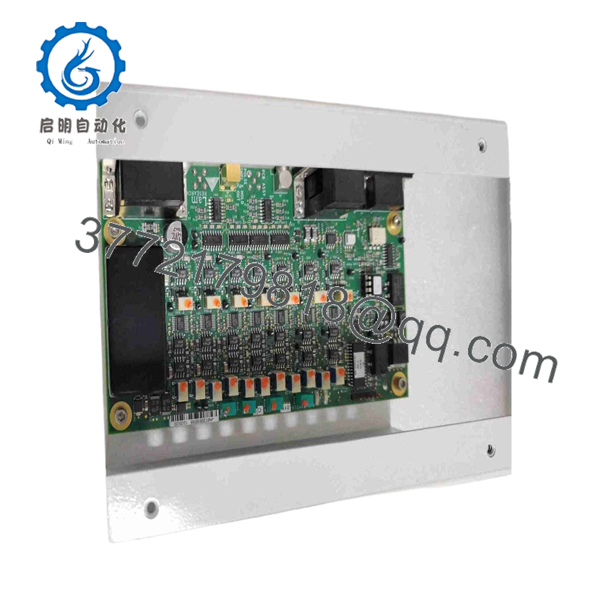
810-048219-015
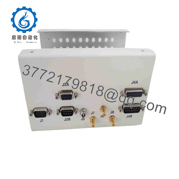
810-048219-015
Installation & Configuration Guide
Estimated replacement time: 30–60 minutes for an experienced semiconductor-equipment technician, excluding tool qualification.
Stage 1: Pre-Installation Preparation
⚠️ Safety First
- Place the Lam Research tool in its approved maintenance state.
- Stop active wafer processing.
- Follow the equipment-specific shutdown sequence.
- Apply electrical LOTO and isolate any associated pneumatic, vacuum, RF, or process-gas energy.
- Verify the cabinet is safe to service.
- Follow fab ESD and contamination-control procedures.
Tools Required
- ESD wrist strap
- Cleanroom gloves
- Phillips/appropriate precision screwdriver
- Digital multimeter
- Connector labels
- Camera or smartphone
- Torque-controlled driver where specified
- Current equipment configuration backup
Data Backup
Before removing the existing board:
- Photograph the complete PCB.
- Record 810-048219-015.
- Record the board revision.
- Photograph all connectors and cable routing.
- Record the board location within the equipment.
- Record current tool alarms.
- Save the applicable equipment configuration.
- Photograph jumpers, switches, or adjustable components if present.
⚠️ Do not assume the replacement board has the same configuration as the board being removed.
Stage 2: Removing the Old Module
- Confirm the tool has reached the approved maintenance state.
- Verify electrical isolation.
- Confirm any associated stored energy has been removed.
- Photograph the board before disconnecting it.
- Label every connector.
- Disconnect connectors by their housings.
- Remove PCB mounting hardware.
- Lift or slide the board out without flexing it.
- Place the removed PCB in an ESD-safe bag.
Inspect:
- Connector pins
- Board edge contacts
- Mounting holes
- Cable assemblies
- Heat-discolored components
- Contamination
- Corrosion
- Cracked solder joints
Estimated time: 10–20 minutes.
Stage 3: Installing the New Module
- Verify the replacement label reads 810-048219-015.
- Compare the board revision with the removed unit.
- Compare connector positions.
- Compare component layout.
- Wear the ESD wrist strap.
- Install the PCB without forcing any connector.
- Secure the board using the original mounting hardware.
- Reconnect each cable according to the photographs.
- Verify connector locks.
- Confirm grounding or bonding connections where applicable.
Configuration Clone — Critical
Before applying power:
- Compare all jumpers with the old board.
- Compare DIP switches, if fitted.
- Check adjustable potentiometers or selector settings, if fitted.
- Verify any synchronization configuration.
- Confirm that no connector has been moved to an adjacent position.
Self-Checklist
- 810-048219-015 verified
- Revision verified
- Board orientation confirmed
- Connector positions matched
- Cables fully seated
- Mounting hardware secured
- Configuration copied
- ESD precautions maintained
Stage 4: Power-On & Testing
- Perform a visual inspection before energizing.
- Check for loose hardware or foreign objects.
- Restore equipment power according to the Lam Research procedure.
- Observe board indicators, if fitted.
- Check host-equipment diagnostics.
- Verify the pulse-sample/hold function through the approved service diagnostic.
- Verify the synchronization output.
- Check for communication or timing-related alarms.
- Compare measured behavior with the original board’s documented operating values.
- Run the equipment’s approved dry-cycle test.
- Complete process qualification before production release.
⚠️ A board that powers up is not necessarily a good board. The pulse-hold and synchronization functions need to be checked at the tool level.
Frequently Asked Questions (FAQ)
1. What is Lam Research 810-048219-015?
It is a Lam Research PCB assembly identified as “PCB ASSY, PULSE SMPL & HOLD W/ SYNC OUT.” This description appears consistently across multiple industrial spare-parts records.
2. What does “Pulse SMPL & HOLD” mean?
It refers to a pulse sample-and-hold function: the board samples a pulse-related electrical signal and maintains the required value for downstream circuitry. The assembly also provides a documented synchronization output. The exact timing characteristics should be taken from the applicable Lam Research equipment documentation rather than inferred from the part number.
3. Is 810-048219-015 a general-purpose I/O board?
No. It is a tool-specific semiconductor-equipment PCB assembly. Treating it like a standard PLC digital I/O card would be inappropriate because its documented function is pulse sample/hold and synchronization.
4. Is 810-048219-015 the same as 810-048219-004?
No. 810-048219-004 is separately listed as a Pulse Power Sample and Hold Assembly, while 810-048219-015 is identified as the Pulse Sample & Hold with Sync Out assembly. Similar numbering does not establish interchangeability.
5. Is 810-048219-015 the same as 810-048219-008?
Again, do not assume so. Public inventory records identify 810-048219-008 separately as a PCB Pulse PRP Sample-Hold board. The different suffix indicates a different assembly configuration or application.
6. Is Revision C available?
Yes, at least one current secondary-market listing specifically identifies an 810-048219-015 Rev C board. However, this does not establish that Rev C is the only or latest revision, nor that it is interchangeable with another revision. Verify the revision against the equipment BOM.
7. What condition is available?
The aftermarket contains used, pre-owned, new-surplus, and potentially refurbished examples. One current listing describes the unit as used and explicitly sells it as-is without warranty, while another pre-owned listing states that untested parts are sold as-is and that testing/refurbishment may be available separately.
For production equipment, specify New Original/New Surplus or Refurbished Tested and request a functional test report. Do not accept an unspecified “used” condition for a timing-sensitive control PCB.



