
 WhatsApp: +86 16626708626
 Email:
  Phone: +86 16626708626
Description
Key Technical Specifications
- Manufacturer: LAM Research
- Manufacturer Part Number: 810-091934-00
- Common Board Identification: Arm Drive Interface Board Assembly
- Related Marking to Verify: 810-91934 REV 1 or equivalent assembly revision
- Product Category: Semiconductor-tool motion-control interface PCB
- Primary Function: Routes command, enable, status, and feedback signals between the tool controller and arm-drive hardware
- Typical Application: Wafer-handling arm, transfer-arm, or related motion-axis control within LAM semiconductor processing equipment
- Installation Type: Chassis- or backplane-mounted board assembly; exact mechanical arrangement must match the removed unit
- Power Architecture: Control/interface board; verify rack supply voltage, connector pinout, and site schematic before installation
- Communications: Not confirmed as a fieldbus device; do not assume EtherNet/IP, Profibus DP, or Modbus support without the applicable LAM tool documentation
- Firmware/Revision Control: Revision-sensitive; record all board markings, firmware identifiers, jumpers, and switch settings before replacement
- Product Status: Legacy/obsolete spare part, generally supplied through surplus inventory rather than current OEM production
Public surplus references identify this part as a LAM Research arm drive interface assembly, but a complete OEM datasheet with electrical ratings, connector definitions, and pin mapping was not publicly available. Match the full part number, board revision, connector layout, and existing tool documentation before ordering.
Product Introduction
The LAM Research 810-091934-00 is an Arm Drive Interface Board Assembly used in LAM semiconductor-processing equipment. It sits in the motion-control signal path between the tool control system and arm-drive hardware, supporting command, enable, interlock, fault, and feedback handling for wafer-transfer or actuator-arm axes.
Buyers normally source this board when an arm axis faults, loses enable, reports intermittent feedback, or cannot complete homing. The exact 810-091934-00 number and installed board revision matter more than a generic “LAM control board” description; this is a revision-sensitive replacement item.
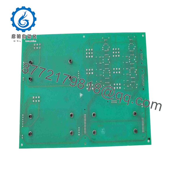
810-091934-00
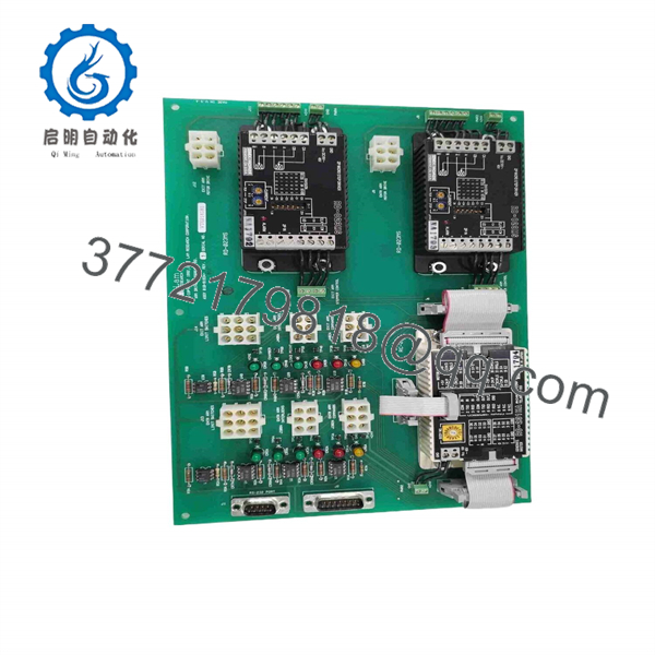
810-091934-00
Troubleshooting Quick Reference
| Symptom | Possible Cause | Relevance to this Part | Quick Check Method | Recommendation |
|---|---|---|---|---|
| No LEDs or no arm response after tool power-up | Missing rack power, blown cabinet fuse, failed power supply, loose backplane connection | ❌ Low to medium | With the tool safely de-energized for connector work, inspect seating and backplane contacts. Under approved service conditions, measure the supply rails at the rack test points using a calibrated Fluke 115 or equivalent meter. | Verify the power supply, fuses, interlocks, and rack voltages before replacing the board. |
| Arm axis shows “Drive Not Ready” or “Servo Enable Missing” | Open safety chain, drive fault, disabled motor amplifier, broken enable wiring | ✅ Medium | Compare the drive-enable signal at the existing board connector against the LAM electrical drawing. Check servo-drive fault LEDs and safety-relay status first. | Do not condemn the interface board until the safety chain and motor drive report healthy status. |
| Arm stops during homing or reports position timeout | Failed encoder, damaged cable, limit-switch issue, mechanical obstruction, missing feedback through interface board | ✅ Medium | Inspect axis limit switches, encoder connections, and cable strain points. Review controller logs and compare feedback behavior with a known-good axis where applicable. | Replace 810-091934-00 only if the controller output and field feedback prove correct at the board boundary but fail through the board. |
| Intermittent arm faults after maintenance | Partially seated connector, bent pin, ESD damage, contaminated contacts, loose harness | ✅ High | Power down under lockout/tagout, remove and inspect each mating connector under magnification, then reseat. Check for oxidation, recessed contacts, heat discoloration, and damaged locking hardware. | Clean and reseat connectors first. If the fault follows the board after connector verification, replace the assembly. |
| Multiple motion signals fail at once | Common control supply issue, backplane fault, controller fault, incorrect replacement revision | ✅ Medium | Compare board markings, revision label, jumper locations, and connector keying to the removed assembly. Check other boards sharing the same rack supply. | Confirm exact 810-091934-00 compatibility and board revision before installation. |
| New replacement causes immediate communication or motion fault | Revision mismatch, different jumper configuration, incorrect connector placement, incompatible tool configuration | ✅ High | Photograph the old board before removal. Match every switch, jumper, label, connector position, and revision code. Review alarm history before and after the swap. | Stop commissioning if behavior changes after installation. Reinstall the original board if safe, then verify compatibility with the tool documentation. |
| Arm drive faults only under motion load | Motor-drive issue, cable intermittency, mechanical binding, thermal issue, weak control signal interface | ✅ Medium | Run the approved diagnostic motion sequence and capture fault logs. Inspect the motor drive, motor cable, encoder cable, and mechanical travel before replacing the board. | A board swap may help, but load-related faults are often outside the interface PCB. |
| Burn marks, corrosion, odor, or damaged connectors on board | Electrical overstress, liquid ingress, contamination, ESD event, failed external drive circuit | ✅ High | Inspect both sides of the board and all connector housings with power removed. Do not energize a visibly damaged board. | Replace the board and investigate the upstream drive, power rails, grounding, and harnesses so the replacement does not fail again. |
❗ Firmware and revision mismatch: I have seen technicians replace a motion interface board, then spend two days chasing an apparent “Communication Timeout” that was really a revision or configuration mismatch. Record every label and revision code before pulling the original.
❗ DIP switches and jumpers: Take photos before touching anything. Seriously. A default jumper position can change an address, signal mode, termination setting, or interlock path.
❗ Connector and wiring mismatch: Do not wire from memory. A close-looking LAM board or revision may use a different pin assignment. Verify every connector against the applicable LAM drawing.
❗ Power-budget check: Confirm the rack supply is healthy under load and leave a 20% current margin. A marginal supply can imitate an interface-board failure.
❗ ESD protection: Wear a grounded wrist strap and handle the board only by its edges. One uncontrolled static discharge can damage an input device with no visible evidence.
Keep these checks in mind and you will avoid most unnecessary board swaps and typical rework time. If the fault remains unclear, send technical support clear photos of both board labels, connectors, alarm screens, and diagnostic logs before ordering.
Frequently Asked Questions
Is LAM 810-091934-00 a direct replacement for any arm-drive board?
Only when the installed assembly matches the full LAM Research part number, board revision, connector arrangement, and tool configuration. A public surplus listing associates the part with an Arm Drive Interface Board Assembly, including a related 810-91934 REV 1 marking, but that does not prove interchangeability across every LAM tool or revision. Verify the removed board label and LAM equipment documentation first.
Can I hot-swap the 810-091934-00 board?
No. Do not assume this board supports hot swapping. It is part of a motion-control and drive-interface path; removing it energized can create signal transients, damage the board or backplane, and leave the arm axis in an unsafe state. Apply the site lockout/tagout procedure, discharge stored energy as required by the tool manual, and confirm the rack is de-energized before removal.
Will I lose programming or tool configuration when I replace it?
The board itself appears to be an interface assembly rather than the primary tool controller, so the main process recipe and PLC/motion program may reside elsewhere. Still, do not assume it contains no configuration. Photograph DIP switches, jumpers, revision stickers, cable positions, and any onboard identifiers before removal. If the LAM system exposes board parameters through service software, save screenshots and diagnostic logs before the swap.
What symptoms actually justify replacing this board?
Replace it when you have evidence that the controller command reaches the board, field wiring and the servo drive are healthy, but the expected command or feedback does not pass through the board. Burn marks, corrosion, failed onboard status indication, repeatable faults that follow the board, or verified signal loss across the board boundary are strong replacement indicators. A dead arm axis alone is not enough; power supply, safety chain, drive faults, encoder feedback, limit switches, and harnesses cause many similar symptoms.
Is this item obsolete, and how does that affect availability?
Treat 810-091934-00 as a legacy semiconductor-tool spare part. Availability typically depends on surplus inventory, recovered equipment, or tested refurbishment stock rather than active OEM production. Confirm actual stock, condition, photographs, board revision, and lead time before issuing a purchase order. For critical uptime spares, buy the exact matching part number and keep it labeled with the supported tool and rack location.
Is the unit New Original, New Surplus, or Refurbished?
The condition must be stated on the specific quotation or product page. “New Original / New Surplus” should mean unused OEM-manufactured inventory that may come from discontinued stock, excess inventory, or a closed project. “Refurbished” should mean a previously used unit that has been cleaned, inspected, functionally tested, and documented. Do not accept vague wording such as “good condition” for a motion-control board.
Why can a surplus unit cost less than factory supply?
Surplus inventory may come from canceled fab expansions, spare-part liquidations, decommissioned tools, or warehouse stock held after a product becomes obsolete. Lower price does not automatically mean an inferior part, but the supplier should provide clear photos, full label details, condition disclosure, test scope, warranty terms, and traceability where available. A board with unknown revision or no test evidence is not a low-cost spare if it extends tool downtime.
What testing should I request before purchase?
Request documented inbound inspection, serial and label photographs, connector-condition photos, ESD-controlled handling, and a functional test report where a compatible test fixture exists. For a live test, ask whether the supplier verified power-up behavior, board status indicators, command/feedback paths, and continuous operation under realistic load. If no genuine LAM rack or simulator is available, the supplier should say so plainly rather than claiming a full system test.



