
 WhatsApp: +86 16626708626
 Email:
  Phone: +86 16626708626
Description
Key Technical Specifications
| Parameter | Specification |
| Manufacturer | Lam Research Corporation |
| Part Number | 810-099175-012 |
| Board Classification | LonWorks Node Circuit Board Assembly |
| Input Voltage | 24 V DC nominal (±10%) |
| Power Consumption | 15 W maximum |
| Network Protocol | LonWorks ANSI/CTA-709.1 fieldbus protocol |
| Operating Temperature | −20 °C to +60 °C (−4 °F to +140 °F) |
| Storage Temperature | −40 °C to +85 °C (−40 °F to +185 °F) |
| Humidity Range | 5% to 95% non-condensing |
| Bus/Interface Connections | Gold-plated edge and multi-pin header connectors |
| Chassis Compatibility | Lam Research Etch, CVD, and Thin-Film Deposition Tool Racks |
Product Introduction & Supply Chain Strategy
The Lam Research 810-099175-012 control module manages real-time fieldbus signal orchestration across semiconductor process chambers. It controls sensor feedback loops and actuator timing in etching and deposition tools where deterministic execution directly impacts wafer yield.
Procuring this board as New Surplus preserves operational readiness without incurring standard OEM lead times on end-of-life hardware. Refurbished alternatives present latent thermal fatigue and degraded solder joints that risk sudden chamber shutdowns. Keeping 1 to 2 units on-site as strategic buffer stock prevents costly unscheduled tool downtime in high-volume fab lines.
Installation & Configuration Guide
WARNING: High-Voltage & Static Sensitivity Hazard
Turn off all power to the semiconductor equipment card cage and wear a grounded ESD wrist strap before touching this assembly to prevent immediate electrostatic discharge damage.
Stage 1: Pre-Installation (Prep & Safety)
- Perform Lock-Out/Tag-Out (LOTO) procedures on the wafer tool power distribution unit (PDU).
- Use a calibrated digital multimeter to verify zero potential across local 24 V DC power bus terminals.
- Photograph all node ID DIP switches, jumper positions, and cable routing on the old board prior to extraction.
Stage 2: Removal
- Loosen all panel retention screws on the card faceplate.
- Disengage the top and bottom ejector handles simultaneously to unseat the board from the backplane.
- Pull the card straight out along the guide rails to prevent twisting or bending backplane pins.
Stage 3: Installation (Clone & Seat)
- Replicate DIP switch configurations and jumper settings from the old board onto the 810-099175-012.
- Align the PCB with the enclosure guide tracks and push smoothly inward until it contacts the backplane header.
- Press both ejector levers flush against the panel to lock the connector into place, then tighten faceplate screws.
Stage 4: Power-On & Testing
- Restore 24 V DC power to the card cage and observe the LED boot sequence.
- Confirm the Power/Status LED shows solid green and communication activity LEDs flash normally.
- Run a network node test through the tool’s software diagnostic system to confirm active communication.
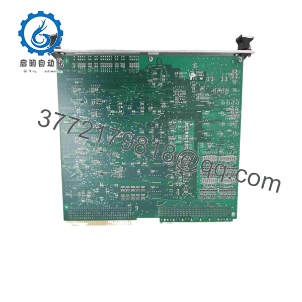
810-099175-012
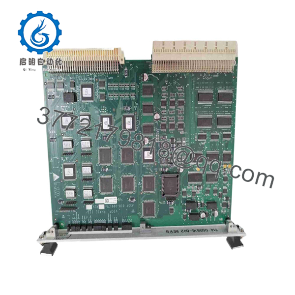
810-099175-012
Firmware/Software Versions & Upgrade Notes
- Recommended Firmware Version: Revision 4.10 or system-matched LonWorks image.
- Compatibility Notice: Software revisions must match overall tool firmware requirements; mismatched versions can cause node registration timeouts or recipe aborts.
- Upgrade/Downgrade Caution: Never perform firmware flashes while the board is installed in an active production rack. Flashing over an active backplane can corrupt bootloader routines—always program and verify revision levels on an offline test rig.
Frequently Asked Questions (FAQ)
Is this 810-099175-012 PCB genuinely brand new, or has it been pulled from a decommissioned tool?
This is a New Surplus unit. It has never been installed or operated in a live semiconductor manufacturing environment. All stock comes from verified spare parts reserves or cancelled fab projects. Each unit passes physical inspection and static verification in original ESD packaging without secondary board repair.
Why should we choose New Surplus over a refurbished or repaired module?
Refurbished modules frequently carry hidden stress from extended thermal cycles and aged passive components. Thermal fatigue in surface-mount components can lead to intermittent micro-faults during chamber processing. New Surplus provides full OEM reliability (10–15 years operational life) while avoiding high OEM list pricing.
Is this card safe to hot-swap while the tool is powered?
No. Hot-swapping is not supported on non-hot-plug backplane architectures. Removing or inserting this module under power can generate electrical arcs, blow internal fuses, or corrupt memory registers on neighboring system cards. Always isolate power before replacing hardware.
How do I transfer the node address to the new 810-099175-012 card?
The node address is determined by physical DIP switches and jumpers located directly on the PCB. Match the exact switch patterns from your original card to the new assembly prior to installation so the master controller recognizes the node automatically.
What warranty protection is included with this New Surplus board?
Every 810-099175-012 card includes a 1-year replacement warranty. If a hardware defect or failure occurs under normal operating conditions, we replace the unit immediately from our on-hand inventory to keep tool downtime minimal.



