
 WhatsApp: +86 16626708626
 Email:
  Phone: +86 16626708626
Description
Key Technical Specifications
| Parameter | Value |
|---|---|
| Manufacturer | LAM Research |
| Part Number | 810-225420-002 |
| Board Type | PCBA |
| Functional Description | LonWorks, 6-Port RS-232 Node |
| Communication Network | LonWorks |
| Serial Interfaces | 6 × RS-232 |
| Application | LAM semiconductor equipment |
| Product Category | Semiconductor equipment control / communication board |
| Installation | Equipment-specific internal PCBA |
| Firmware | Not publicly verified; confirm installed revision before replacement |
| Mechanical Dimensions | Not publicly verified; verify against OEM equipment documentation |
| Power Requirements | Not publicly verified; verify equipment-specific electrical documentation |
| Operating Temperature | Not publicly verified for this exact assembly |
| Connector Pinout | Equipment-specific; verify against the applicable LAM wiring documentation |
| Replacement Status | Verify exact equipment compatibility before purchase |
A semiconductor-equipment parts inventory specifically lists 810-225420-002 as “PCBA, Lonworks, 6 Port RS-232, NODE.” The same identification appears in another semiconductor-equipment parts database.
Important specification note: Several online listings incorrectly or inconsistently describe this part as a generic printed circuit board or as a high-speed DAQ module. Those descriptions conflict with the more specific parts-inventory identification. For procurement and replacement purposes, the exact board marking, assembly number, connector arrangement, and equipment configuration should take precedence.
Product Introduction
The LAM Research 810-225420-002 is a PCBA identified in semiconductor-equipment parts inventories as a LonWorks node with six RS-232 ports. It is used as an equipment-level communication/control assembly rather than as a general-purpose PLC communication module.
The important point when replacing this board is identification accuracy. Do not substitute another LAM PCB solely because the board has a similar physical format. Verify the complete 810-225420-002 assembly number, connector configuration, equipment model, and installed communication configuration before installation.
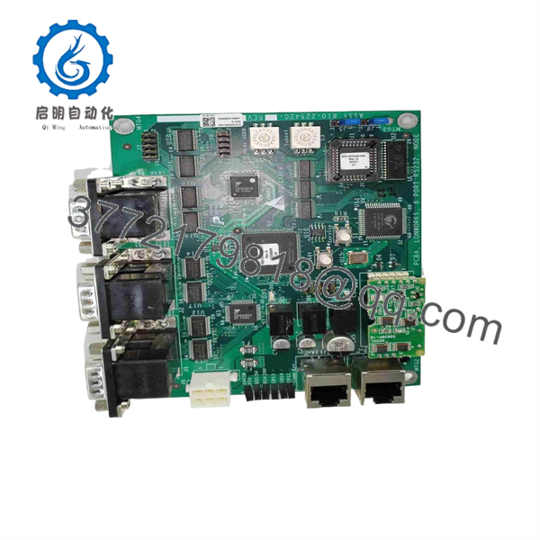
810-225420-002
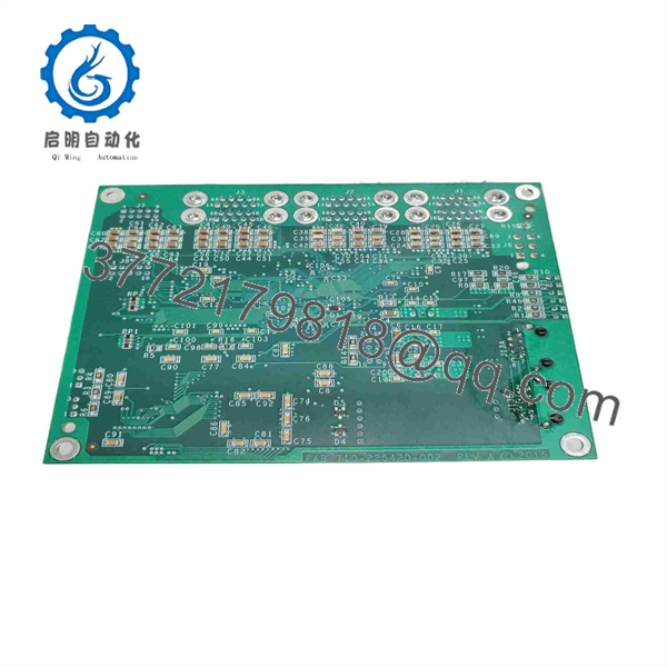
810-225420-002
Installation & Configuration Guide
Stage 1: Pre-Installation Preparation — Approximately 10 Minutes
⚠️ Safety First: Semiconductor processing equipment can contain hazardous voltages, RF energy, vacuum systems, heated components, moving mechanisms, and stored electrical energy. Follow the equipment manufacturer’s maintenance procedure and your site’s lockout/tagout procedure before accessing the board.
Tools Required
- ESD wrist strap and grounded ESD workstation
- Appropriate Phillips/flat-head screwdriver
- Digital multimeter
- Wire and connector identification labels
- Camera or smartphone for documentation
- Equipment service documentation
- Replacement LAM 810-225420-002
Data Backup
Before removing the existing board:
- Record the complete board part number.
- Photograph the board from several angles.
- Photograph every connector before disconnection.
- Record cable and connector identifiers.
- Photograph DIP switches, jumpers, rotary switches, and configuration links if present.
- Record the equipment model and controller configuration.
- Record any node address or communication settings that are accessible.
- Retain the removed board until the replacement has passed functional testing.
Do not rely on memory for connector locations. A six-port RS-232 communication assembly can have multiple visually similar connectors.
Stage 2: Removing the Existing Module — Approximately 5–10 Minutes
- Place the equipment into its approved maintenance state.
- Complete the site’s electrical isolation procedure.
- Verify that the board is de-energized using the approved measurement procedure.
- Attach your ESD protection.
- Photograph the installed board and cable routing.
- Label each connector before removal.
- Disconnect the cables without pulling on individual conductors.
- Release the board’s retaining hardware.
- Remove the PCBA straight and carefully.
- Place the original board in an ESD-safe container.
⚠️ Do not discard the original board immediately. Keep it available for connector, jumper, label, and revision comparison.
Stage 3: Installing the New 810-225420-002 — Approximately 5–10 Minutes
1. Verify the Assembly
Confirm that the replacement is marked:
810-225420-002
Do not accept a substitution based only on a seller’s statement that another board is “equivalent.”
2. Compare the Boards
Place the old and replacement boards side by side and compare:
- Part number
- PCB revision
- Connector positions
- Connector labels
- Component population
- Jumpers
- Switch settings
- Mounting holes
- Identification labels
- Cable interfaces
3. Clone Configuration
If the original assembly contains configurable switches or jumpers, reproduce the original settings exactly unless the applicable LAM service documentation specifies a different configuration.
4. Install the PCBA
- Align the board with its mounting guides.
- Ensure that no cable or connector interferes with insertion.
- Seat the board without excessive force.
- Install the original retaining hardware.
- Reconnect all cables according to the photographs and labels.
- Verify that each connector is fully seated.
Self-Checklist
- Exact 810-225420-002 part number confirmed
- PCB revision compared
- Connector positions verified
- Cable labels verified
- Switch/jumper configuration copied
- Board retaining hardware installed
- All connectors fully seated
- ESD precautions maintained
Stage 4: Power-On & Functional Testing — Approximately 10–20 Minutes
Pre-Power Check
Before restoring power:
- Inspect the board for physical damage.
- Check for loose hardware.
- Check all connectors.
- Confirm that no conductive debris is present.
- Verify that the board is correctly seated.
- Check the applicable supply rails according to the equipment service manual.
Power-Up
- Restore equipment power according to the approved maintenance sequence.
- Observe board indicators, if fitted.
- Allow the equipment controller to complete its initialization sequence.
- Check communication status.
- Verify the six RS-232 interfaces according to the equipment’s diagnostic procedure.
- Confirm LonWorks network communication.
- Check for communication faults or node alarms.
- Run the equipment’s approved functional test.
Troubleshooting
No communication:
Check connector seating, cable identification, node addressing, serial configuration, and the upstream controller interface.
One RS-232 channel fails:
Check that specific port’s cable and connected device before condemning the PCBA.
Multiple RS-232 channels fail simultaneously:
Check board power, common communication hardware, configuration, and LonWorks network status.
Board is not recognized:
Verify the exact assembly number and equipment compatibility. Do not assume that a visually similar LAM PCBA is interchangeable.
Intermittent communication:
Inspect connector seating, cable shielding/grounding, serial cabling, and network configuration. Compare the replacement board’s revision with the removed board.
Replacement Pitfalls Engineers Should Check
❗ 1. Wrong Functional Description
A common procurement problem is buying a board based on a generic description such as “LAM PCB.”
The 810-225420-002 has a more specific documented identification: PCBA, LonWorks, 6 Port RS-232, Node.
The distinction matters. LAM uses many PCB assemblies with similar numbering formats, and a mechanically similar board is not automatically electrically or functionally compatible.
❗ 2. Conflicting Online Specifications
Some online listings describe 810-225420-002 as a high-speed DAQ module with specifications such as 24-bit analog inputs and 10 Gigabit Ethernet. Those claims conflict with the parts inventories that identify the same part number as a six-port RS-232 LonWorks node.
For this reason, those DAQ specifications should not be used as purchasing specifications without confirmation from LAM documentation or the installed equipment.
❗ 3. Connector Configuration
Do not assume RS-232 connectors are interchangeable simply because they use the same general serial standard.
Connector pin assignments, signal direction, grounding, and cable assemblies are equipment-specific.
❗ 4. Configuration Retention
If the original board contains node-address or communication configuration, photograph it before removal.
A replacement board with different configuration can produce a communication failure even when the hardware itself is functional.
❗ 5. ESD Damage
This is a semiconductor-equipment control board. Treat it as ESD-sensitive electronic hardware.
Use a grounded wrist strap and ESD-safe handling procedures. Do not handle exposed circuitry unnecessarily.
Frequently Asked Questions (FAQ)
Can I hot-swap the LAM 810-225420-002?
Do not assume that it is hot-swappable. The available public identification confirms the board’s communication function but does not establish a hot-swap capability. Unless the applicable LAM equipment documentation explicitly permits replacement under power, isolate the equipment before removing the PCBA.
What exactly is the LAM 810-225420-002?
Public semiconductor-equipment inventories identify it as “PCBA, Lonworks, 6 Port RS-232, NODE.”
That is the most specific public functional description located for this exact part number.
Is 810-225420-002 a DAQ module?
There are online listings that describe it as a high-speed DAQ module. However, those listings provide specifications that conflict with other sources. A separate semiconductor-parts inventory specifically identifies 810-225420-002 as a six-port RS-232 LonWorks node.
For procurement, treat the six-port LonWorks/RS-232 identification as the documented description unless the applicable LAM equipment documentation confirms otherwise.
Is LAM 810-225420-002 obsolete?
The public sources reviewed do not provide a definitive OEM lifecycle statement for this exact assembly. Availability therefore needs to be checked against current inventory rather than assuming either active or obsolete status.
Can another LAM PCB replace 810-225420-002?
Do not substitute another part number without compatibility documentation. Verify the equipment platform, connector arrangement, communication architecture, board revision, and applicable LAM service documentation.
Will I lose my equipment configuration when replacing the board?
That depends on where the configuration is stored. Do not assume that configuration is retained by the replacement board or automatically downloaded by the host controller.
Record all accessible communication settings before removing the original assembly.
Why can surplus 810-225420-002 boards vary in condition?
Industrial semiconductor-equipment parts can appear in several inventory conditions, including new surplus and previously installed equipment. The seller should state the actual condition rather than simply using “original.”
For a used board, request photographs of the actual unit, board markings, connectors, and any available functional-test documentation.
What should I provide when requesting a replacement?
Provide:
- LAM 810-225420-002
- Equipment/tool model
- Existing board revision, if visible
- Photos of the complete board
- Connector photos
- Existing communication configuration
- Required condition: New Original, New Surplus, or Refurbished
- Required quantity
- Required delivery date
This information gives the supplier enough detail to distinguish the required PCBA from similarly numbered LAM assemblies.



