
 WhatsApp: +86 16626708626
 Email:
  Phone: +86 16626708626
Description
Key Technical Specifications
- Manufacturer: LAM Research
- Manufacturer Part Number: 810-520659-001
- Product Identification: SER I/O 6-Channel PCB
- Product Type: Serial I/O interface PCB assembly
- Channel Count: Six serial I/O channels
- Primary Function: Provides serial communications and signal-interface paths between the LAM tool controller and compatible peripheral equipment
- Typical Application: Internal control architecture of LAM Research semiconductor etch, deposition, vacuum, or wafer-processing systems
- Installation Type: Internal controller chassis or electronics-rack PCB assembly
- Serial Interface Type: Public market descriptions reference serial I/O operation; verify whether the installed tool uses RS-232, RS-422, RS-485, or proprietary electrical signaling before replacement
- Signal Handling: Tool-specific serial data, command, status, handshake, and peripheral communications
- Firmware/Revision Control: Verify all PCB revision markings, programmable-device labels, jumpers, and configuration settings against the removed unit
- Handling Requirement: ESD-controlled handling and packaging required
- Lifecycle Status: Legacy semiconductor-equipment spare part; availability depends on surplus, used, or tested inventory
Available product records consistently identify 810-520659-001 as a LAM Research SER I/O 6-Channel PCB. One supplier describes it as a six-port serial interface assembly; however, public sources do not establish an OEM-approved electrical pinout, voltage rating, UART type, or universal protocol assignment. Confirm those details using the specific LAM tool schematic and the original board label.
Product Introduction
The LAM Research 810-520659-001 is a SER I/O 6-Channel PCB Assembly used in compatible LAM semiconductor process equipment. It supports multiple internal serial communication paths between the tool controller and connected subsystems, helping carry command, status, handshake, and diagnostic data within the equipment electronics architecture.
This board is an exact-part-number maintenance spare, not a generic serial card. Its six-channel configuration makes it relevant when several related serial devices drop offline or show intermittent communication faults. Match the complete 810-520659-001 number, PCB revision, connector layout, and installed tool configuration before purchase.
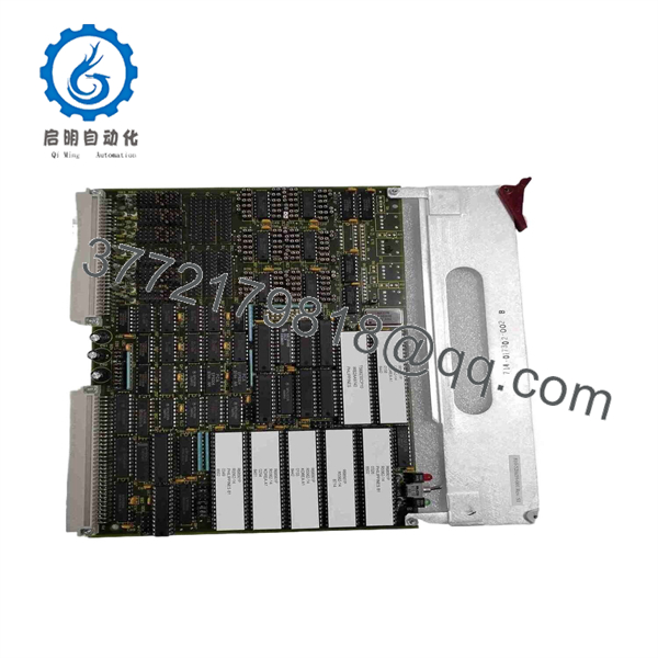
810-520659-001
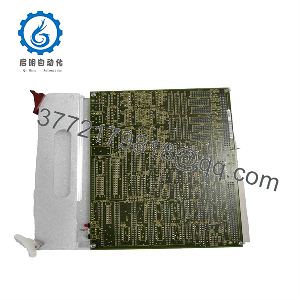
810-520659-001
Troubleshooting Quick Reference
| Symptom | Possible Cause | Relevance to this Part | Quick Check Method | Recommendation |
|---|---|---|---|---|
| One peripheral reports a serial communication timeout | Failed peripheral, loose serial cable, incorrect address, damaged connector, individual board channel failure | ✅ Medium | Review the tool diagnostic log for the affected channel. With power removed, inspect the cable, connector retention, pin condition, and shield termination at both ends. | Test the field device and cable first. Replace the board only if the fault remains on the same board port with verified wiring. |
| Several serial devices fail at the same time | Controller fault, common power problem, harness disconnect, board failure | ✅ High | Identify whether the failed devices share the 810-520659-001 board or one connector group. Verify controller status and applicable rack supply rails with a calibrated meter. | A common six-channel board fault is possible, but verify power and the shared harness before replacement. |
| Tool boots but attached subsystem does not initialize | Incorrect baud rate, address mismatch, failed device, configuration loss, serial interface fault | ✅ Medium | Capture startup logs before cycling power. Compare device configuration, board jumpers, and cable routing with maintenance records or a known-good channel. | Do not replace the board until the subsystem configuration and device power are confirmed. |
| Repeated communication errors occur only during processing | Electrical noise, shield-grounding error, cable intermittency, thermal fault, degraded serial channel | ✅ Medium | Correlate alarms with motor, RF, vacuum-pump, or valve activity. Inspect cable shields and grounding per the LAM drawing; check for strain at cabinet door and motion points. | Correct grounding and harness issues first. Replace the board if errors remain tied to one physical channel. |
| No response from all connected serial devices | Missing board supply, improperly seated board, controller communication failure, major board logic fault | ✅ High | Verify documented rack power rails and inspect board insertion, edge contacts, and retention hardware under lockout/tagout. Review controller diagnostics for a board-level alarm. | Reseat and inspect the board. Replace it if verified supply and controller operation are present but all six channels remain inactive. |
| Replacement board causes new serial faults | Incorrect revision, jumper mismatch, incompatible port wiring, wrong board installed | ✅ High | Before removal, photograph every connector, jumper, label, and port assignment. Compare the replacement board side by side with the original. | Stop commissioning and verify the full board revision and harness mapping. Do not force any connector. |
| Random faults after cabinet service | Loose connector, ESD damage, pin pushed back in shell, swapped cable, missing shield bond | ✅ Medium | Inspect each connector under magnification and verify port-to-device mapping against labels. Check that cable backshells and shield terminations are secure. | Reseat cables and correct port mapping before considering a board replacement. |
| Board has burned components, corrosion, or damaged connectors | Overvoltage, shorted external device, contamination, ESD event, connector damage | ✅ High | Isolate power and inspect both PCB sides. Check mating cable insulation and continuity before installing another board. | Replace the board and locate the external cause; otherwise, the replacement can fail immediately. |
❗ Firmware and revision mismatch: A serial I/O board can fit mechanically while behaving differently in the installed control system. I have seen an “easy” board swap turn into a two-day communication timeout chase because the replacement revision did not match the controller configuration. Record every label before removal.
❗ Jumpers and port assignment: Take clear photos of the original board, jumper locations, connector labels, and cable positions. It is the most common rookie mistake, and it happens constantly. A cable on the wrong serial channel may look like a failed board.
❗ Do not wire from memory: Serial interface connectors can use different pinouts, voltage standards, signal grounds, or shield arrangements. Check the LAM electrical documentation, especially where RS-232 and differential serial wiring coexist.
❗ Supply rails still matter: A brownout can create serial framing or handshake errors that look exactly like board failure. Measure the rack supply during startup and when the tool is under normal electrical load. Maintain at least a 20% power-supply current margin.
❗ ESD can kill a port silently: Use a grounded wrist strap and an ESD-safe work surface. I have watched a technician handle a high-value card during dry weather, power it up, and lose one communications channel immediately. Use the strap.
Keep these checks in mind and you will save yourself most typical rework time. If the diagnosis remains uncertain, contact technical support with photos of both board sides, all label markings, the affected port numbers, exact alarms, and startup diagnostic logs.
Frequently Asked Questions
What is the LAM 810-520659-001 used for?
The LAM Research 810-520659-001 is identified as a SER I/O 6-Channel PCB used in LAM semiconductor-equipment control systems. It provides multiple serial I/O communication paths for connected tool subsystems and peripherals. Its exact connected devices, electrical interface standard, and port assignment depend on the LAM tool model and installed configuration.
Does the board use RS-232, RS-422, or RS-485?
Do not assume a universal interface standard from the “SER I/O” description. One public product description references six RS-232/RS-422 serial channels, but that claim is not a substitute for an OEM schematic or a board-specific manual. Verify the electrical signaling, pinout, baud rate, parity, handshaking, and shielding arrangement for your exact tool before connecting equipment.
Can I hot-swap the 810-520659-001 board?
No. Treat it as non-hot-swappable unless the specific LAM equipment manual explicitly permits live replacement. Pulling a serial I/O PCB under power can create corrupted data, communication faults, or electrical damage to the board, backplane, and connected peripheral electronics. Shut down the tool using the approved procedure, apply lockout/tagout, and observe ESD controls.
How can I tell if the PCB has failed rather than the field device?
Start at the field device. Confirm its supply voltage, local status indicators, device alarm state, cable integrity, connector pin condition, and configuration. Then identify whether the fault follows one board port or affects several ports sharing the same 810-520659-001. If a known-good device and cable fail only on one specific board channel, or all channels fail with verified rack power and controller operation, the PCB becomes the likely source.
Will a replacement board retain my serial settings?
Do not assume it will. Some settings may reside in the system controller, while others can be determined by jumpers, onboard components, or board revision. Before removal, photograph the original board, record all part and revision markings, note jumper positions, and document every cable-to-port assignment. Save tool diagnostic screens and configuration records where available.
Is 810-520659-001 obsolete?
It should be treated as a legacy LAM semiconductor-equipment spare. Current availability is likely to come from new-surplus, used, recovered, or tested refurbishment inventory rather than routine factory production. Confirm real-time quantity, condition, photos, revision, and delivery lead time before you place a purchase order.
Why is a New Surplus board less expensive than a factory replacement?
New Surplus inventory can originate from unused maintenance stock, decommissioned-tool inventories, canceled projects, or warehouse liquidations. The lower price does not automatically mean the board is inferior. What matters is whether the supplier clearly discloses the condition, provides label and connector photos, confirms the exact part number, states the testing performed, and provides warranty terms.
What quality checks should I request before buying?
Request inbound traceability review, high-resolution photos of the full label and both PCB sides, inspection for corrosion and rework marks, connector and edge-contact inspection, and ESD-safe packaging confirmation. For a tested unit, ask whether the supplier performed power-on checks, channel communication verification, connector continuity inspection, and an extended runtime test. If a genuine compatible LAM test rack is unavailable, the supplier should disclose that limitation rather than claim full in-tool functional testing.



