
 WhatsApp: +86 16626708626
 Email:
  Phone: +86 16626708626
Description
Key Technical Specifications
| Parameter | Value |
|---|---|
| Manufacturer | LAM Research |
| Part Number | 810-800081-022 |
| Board Identification | P2MB / VME Etch |
| Product Type | PCB Assembly / Motherboard |
| Bus Architecture | VME |
| Application | LAM semiconductor etch equipment |
| System Role | VME backplane / module interconnect |
| Board Revision | Verify from physical board label |
| Compatible Modules | Verify against the specific LAM equipment configuration |
| Power Requirements | Equipment-specific; verify service documentation |
| Mechanical Dimensions | Not sufficiently verified from OEM documentation |
| Connector Configuration | Verify against installed board |
| Firmware | Not established as a board-level specification |
| Condition | New Original / New Surplus / Refurbished — confirm actual unit |
Technical verification note: Public sources disagree on some detailed specifications. One listing calls the part a VMEbus Analog I/O PCBA, another identifies it as a P2MB VME motherboard, and another lists it specifically as a VME BackPlane PCB.
For procurement, the safest identification is the exact LAM 810-800081-022 part number plus the physical board marking. Do not rely on unsupported claims such as specific ADC/DAC resolution, channel count, operating voltage, or hot-swap capability.
Product Introduction
The LAM Research 810-800081-022 is a P2MB/VME PCB assembly associated with LAM Research VME-based etch equipment. Multiple industrial parts sources identify the assembly as a P2MB VME Etch board or VME backplane PCB.
This is a system-specific board, not a generic VME replacement card. Before ordering, match the complete part number, board revision, connector arrangement, and the target LAM tool configuration. A related part number such as 810-800081-018 should not be treated as interchangeable without documentation.
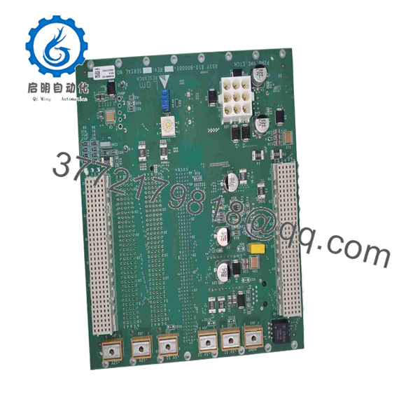
810-800081-022
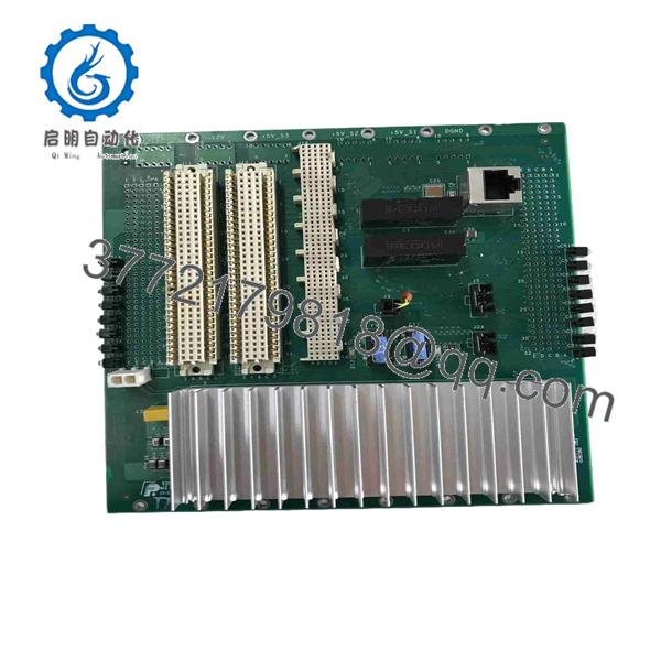
810-800081-022
Installation & Configuration Guide
Stage 1: Pre-Installation Preparation — 10–15 Minutes
⚠️ Safety First: Follow the LAM equipment maintenance procedure and site lockout/tagout procedure. Do not remove a VME board from an energized chassis unless the applicable equipment documentation explicitly permits it.
Tools Required
- ESD wrist strap
- ESD-safe work surface
- Appropriate screwdriver set
- Digital multimeter
- Connector labels
- Smartphone/camera
- LAM equipment service documentation
Data Backup
Before removal:
- Record 810-800081-022 from the existing board label.
- Photograph the entire installed board.
- Photograph all connector locations.
- Record the board revision.
- Photograph jumpers, switches, and configuration links.
- Document the slot position of every installed VME module.
- Record cable routing and harness identification.
Keep the old board until the replacement has passed system-level testing.
Stage 2: Removing the Old Board — 5–10 Minutes
- Place the LAM tool in its approved maintenance state.
- Complete electrical isolation and verify the safe state.
- Apply ESD protection.
- Remove any required chassis cover or access panel.
- Label connected harnesses.
- Disconnect connectors without pulling on the wires.
- Release the board’s retaining hardware.
- Carefully withdraw the PCB from the VME assembly.
- Inspect the connector pins and mating backplane for damage or contamination.
⚠️ Do not force the board. VME connectors can require considerable insertion force, and misalignment can damage connector contacts.
Stage 3: Installing 810-800081-022 — 10 Minutes
1. Verify the Replacement
Confirm:
- Part number: 810-800081-022
- Board identification: P2MB / VME Etch
- Revision marking
- Connector arrangement
- Mechanical dimensions
- Mounting hardware
2. Compare Against the Removed Board
Place both assemblies side by side.
Check:
- PCB layout
- Connector positions
- Connector labels
- Jumper settings
- Switch settings
- Revision markings
- Mounting points
- Daughter-board interfaces
3. Install
- Align the board with the chassis guides.
- Ensure the PCB is correctly aligned with the VME connector.
- Push the board straight into position.
- Confirm full connector engagement.
- Secure the retaining hardware.
- Reconnect harnesses according to your photographs and labels.
Self-Checklist
- Exact part number confirmed
- Board revision checked
- Slot position confirmed
- Connector alignment verified
- Harnesses correctly identified
- Jumpers/switches copied where applicable
- Board retaining hardware secured
Stage 4: Power-On & Testing — 10–20 Minutes
Pre-Power Check
Inspect:
- VME connectors
- PCB edge contacts
- Harness connections
- Mounting hardware
- Foreign material
- Signs of corrosion or component damage
Use the equipment documentation to verify applicable supply rails before energizing.
Power-Up
- Restore power according to the LAM maintenance procedure.
- Observe chassis and controller status indicators.
- Confirm VME system initialization.
- Verify communication with installed VME modules.
- Check for controller or chassis diagnostics.
- Run the equipment’s approved operational test.
- Verify the affected process functions before returning the tool to production.
Troubleshooting
System fails to initialize:
Check board seating, VME connector engagement, slot assignment, power rails, and board revision.
Downstream VME module is not detected:
Inspect the affected slot and backplane connection. Compare the installed configuration with the original photographs.
Intermittent communication:
Inspect connector seating and mechanical alignment first. Then check the applicable VME bus diagnostics.
Replacement appears electrically correct but the tool will not boot:
Stop repeated power cycling. Verify the exact board revision and LAM tool configuration before proceeding.
Frequently Asked Questions (FAQ)
What is LAM 810-800081-022?
Public industrial parts sources identify 810-800081-022 as a LAM Research P2MB/VME Etch PCB, with some sources specifically calling it a VME backplane PCB.
Is 810-800081-022 a VME motherboard or backplane?
The terminology varies between suppliers. One source identifies it as a motherboard, while another lists it as a VME BackPlane PCB.
For purchasing purposes, use the exact 810-800081-022 assembly number and the physical board label rather than relying on the generic term “motherboard” or “backplane.”
Is 810-800081-022 compatible with 810-800081-018?
Do not assume compatibility. A parts catalog separately lists 810-800081-018 REV.B P2 MB VME ETCH and 810-800081-022 VME BackPlane PCB as different part numbers.
Verify the LAM tool model, board revision, connector arrangement, and service documentation before substituting either part.
Can this board be hot-swapped?
Do not assume it can. The public sources reviewed do not establish a verified hot-swap specification for 810-800081-022. Follow the LAM equipment maintenance procedure unless hot replacement is explicitly documented.
Is LAM 810-800081-022 obsolete?
The sources reviewed do not provide a reliable OEM lifecycle statement establishing its current official lifecycle status. Treat it as a legacy/field-service part for procurement purposes and verify actual stock and condition with the supplier.
Why do online specifications for this part conflict?
This is important. Some third-party listings attribute analog I/O specifications to 810-800081-022, while other sources identify it as the /VME Etch motherboard or backplane.
I would not publish unsupported claims such as “16-channel analog I/O,” “16-bit ADC/DAC,” or a specific supply voltage as definitive specifications for this part without the OEM drawing or a verified board photograph.
What should I send a supplier when requesting this part?
Provide:
- LAM 810-800081-022
- Photo of the existing board label
- Board revision
- LAM equipment/tool model
- Photo of the connector side
- Required quantity
- Required condition: New Original, New Surplus, or Refurbished
- Required delivery date
For a legacy VME assembly, the physical board label and revision are particularly important.



