
 WhatsApp: +86 16626708626
 Email:
  Phone: +86 16626708626
Description
Key Technical Specifications
- Manufacturer: LAM Research
- Manufacturer Part Number: 853-049542-173
- Associated PCB Number: 810-028295-173
- Associated Assembly References: 810-028296-173 and 810-028298-004 appear in surplus-record assemblies; verify the physical board and tool bill of materials
- Product Identification: ASSY TEMP CONT 24-CHANNEL / 24 CH TEMP CTLR
- Product Type: Multi-channel semiconductor tool temperature-controller PCB assembly
- Channel Count: 24 independent temperature-control channels
- Primary Function: Interfaces with tool-specific temperature sensing and heater-control circuits used for chamber thermal management
- Typical Application: LAM Research semiconductor etch or deposition equipment thermal-control architecture
- Control Characteristics: Temperature sensing, control output, monitoring, and thermal fault handling; exact sensor type, output type, control algorithm, and heater rating require OEM verification
- Installation Type: Internal tool electronics rack or node-board assembly; match mounting points, connector layout, board revision, and installed configuration
- Supply Requirements: Not publicly verified from an OEM datasheet; confirm all power rails, terminal pinout, protective grounding, and circuit protection from LAM electrical drawings
- Firmware and Configuration: Verify board revision, device labels, calibration/configuration information, jumpers, and any EEPROM or configuration settings before replacement
- Lifecycle Status: Legacy semiconductor-equipment spare part; availability commonly depends on surplus, recovered, used, or tested-refurbished stock
Independent surplus records consistently identify 853-049542-173 as a LAM Research 24-channel temperature-control assembly and link it to 810-028295-173. One reseller also refers to it as a “Node Board, 24 CH TEMP CTLR,” but its detailed claims about control type, direct substitutes, and firmware compatibility are not independently verified by public OEM documentation. Match the physical board and LAM service documentation before installation.
Product Introduction
The LAM Research 853-049542-173 is a 24-Channel Temperature Controller PCB Assembly used in compatible LAM semiconductor process equipment. It supports chamber thermal-control functions by handling temperature-related sensing, control, monitoring, and fault signaling for multiple tool heating or temperature-control zones.
This board is an exact-number thermal-control spare, not a universal PID controller. Buyers typically source it when multiple temperature zones show invalid readings, fail to respond to commands, or generate repeatable controller-related thermal alarms. Match 853-049542-173, associated PCB number 810-028295-173, revision labels, connector layout, and configured tool hardware before purchase.
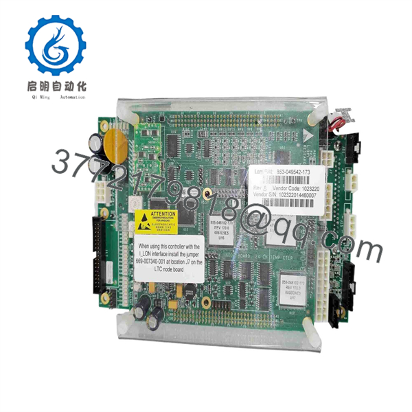
853-049542-173
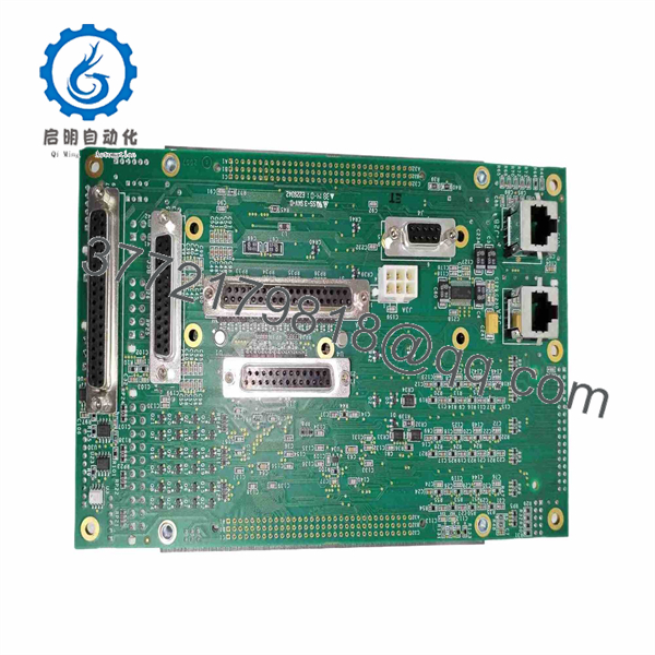
853-049542-173
Troubleshooting Quick Reference
| Symptom | Possible Cause | Relevance to this Part | Quick Check Method | Recommendation |
|---|---|---|---|---|
| One temperature zone reads open, shorted, or implausible | Failed RTD, thermocouple, thermistor, cable break, loose connector, individual input-channel fault | ✅ Medium | Compare the displayed value with an independent calibrated temperature measurement. With power isolated, measure sensor continuity and resistance or thermocouple loop continuity at the field connector and board-side termination. | Check the sensor and harness first. Replace the board only when a verified-good sensor signal reaches the board but is read incorrectly. |
| Several temperature zones fail simultaneously | Common sensor supply issue, disconnected harness, controller supply fault, shared reference failure, PCB fault | ✅ High | Identify whether failed zones share the same connector group or board. Verify applicable rack supply rails and inspect common return and reference wiring against the LAM schematic. | A 24-channel board issue is possible, but rule out shared power, connectors, and harnesses before replacement. |
| Heater zone does not heat when commanded | Open heater, tripped thermal cutoff, failed SSR/contactor, missing heater supply, interlock open, board output fault | ❌ Low to medium | Check the heater power circuit, thermal cutoff, solid-state relay or contactor, and chamber interlocks. Measure commanded and actual output at the documented test points. | Do not replace the controller board until the heater circuit and external switching device are verified. |
| Zone overheats or temperature runs away | Failed heater SSR shorted on, sensor disconnected, incorrect tuning or configuration, wiring error, output-channel fault | ✅ High | Put the affected zone in a safe state immediately according to tool procedures. Compare sensor reading to independent measurement and inspect the external heater switching device for a stuck-on condition. | Treat as a process and equipment safety issue. Verify the SSR/contactor and sensor first; replace the board if its output remains asserted incorrectly. |
| Temperature value is noisy or fluctuates | Poor sensor connection, electrical noise, shield-grounding error, damaged cable, unstable supply, input conditioning fault | ✅ Medium | Trend the value over time and compare it with a known-good zone. Inspect shielding, connector retention, and sensor routing near RF, heater, and motor wiring. | Correct wiring and grounding issues first. Replace the board only if instability remains tied to one board channel. |
| Tool reports thermal-control communication or node fault | Board not seated, rack/backplane fault, controller communication issue, hardware revision mismatch, board logic fault | ✅ High | Record the full alarm text before a power cycle. Inspect board seating, edge contacts, rack connectors, and controller diagnostics under an approved shutdown condition. | Reseat and inspect first. Replace only after the power, backplane, and controller path are confirmed healthy. |
| New board creates different temperature alarms | Incorrect revision, calibration/configuration mismatch, jumper mismatch, connector installed incorrectly, wrong board type | ✅ High | Photograph the original board before removal. Compare all labels, jumper settings, programmable-device markings, connectors, and cable identifiers with the replacement. | Stop commissioning and verify the exact hardware/software configuration. Do not force the board into operation. |
| All zones show incorrect readings after maintenance | Swapped harnesses, common reference disconnected, wrong connector placement, grounding mistake, configuration change | ✅ Medium | Compare every harness position and label with pre-maintenance photographs and the LAM wiring diagram. Check sensor common/reference circuits. | Restore correct wiring and configuration before replacing the controller board. |
| Burn marks, corroded connectors, or damaged PCB components | Electrical overstress, heater circuit fault, liquid or chemical contamination, ESD, external short | ✅ High | De-energize and apply lockout/tagout. Inspect both board sides, connectors, and associated field wiring under magnification. Test heater circuits for shorts before installing another board. | Replace the damaged board and identify the root cause so the replacement does not fail on power-up. |
❗ Do not swap a 24-channel thermal board without documentation: One connector error can move a sensor or heater-control zone to the wrong channel. That can produce an over-temperature alarm, an under-temperature process abort, or a heater zone that responds to the wrong recipe command.
❗ Firmware, calibration, and configuration can matter: Public reseller claims mention a possible “Control Type 3” configuration, but that is not confirmed by OEM documentation. Record all jumper positions, firmware labels, EEPROM identifiers, and service-software configuration before removing the old board.
❗ Check the SSR or contactor before blaming the PCB: A heater output that stays on is often caused by a shorted solid-state relay, not a failed low-level controller board. Confirm the external switching device with the approved electrical procedure before replacing hardware.
❗ Take photos before touching connectors: Photograph all harness labels, cable orientation, shield connections, and board settings. Seriously. It takes two minutes and can prevent days of troubleshooting.
❗ ESD controls are mandatory: Wear a grounded wrist strap and use an ESD-safe work surface. Temperature-input circuits can be sensitive to static damage that does not leave a visible mark.
Keep these checks in mind and you will save yourself 90% of typical rework time. If you remain stuck, contact technical support with board photographs, the full label, exact temperature alarms, affected channel numbers, sensor readings, independent temperature measurements, and controller diagnostic logs.
Frequently Asked Questions
What is the LAM 853-049542-173?
The LAM Research 853-049542-173 is identified in multiple surplus records as a 24-channel temperature controller assembly or 24 CH TEMP CTLR. It is associated with PCB number 810-028295-173 and is used in LAM semiconductor equipment thermal-control applications.
Is 853-049542-173 the same as 810-028295-173?
They are shown together in several market records, indicating that 810-028295-173 is an associated PCB or assembly reference for 853-049542-173. However, do not treat every board carrying one of those numbers as interchangeable until you verify the complete physical label, revision, connector population, and LAM equipment bill of materials.
Can I hot-swap this 24-channel temperature controller board?
No. Do not hot-swap it unless the exact LAM tool manual explicitly permits the procedure. A temperature-control board can influence heater commands, thermal alarms, and chamber process conditions. Removing it energized can create invalid sensor readings, uncontrolled outputs, equipment faults, or process risk. Place the chamber in a safe maintenance state, isolate power according to the approved procedure, and apply lockout/tagout before removal.
How do I know whether the board is bad instead of a sensor or heater?
Start at the field device. Check the sensor condition, connector, cable continuity, measured resistance or thermocouple loop, heater element, thermal cutoff, external SSR or contactor, and heater supply. Compare the board’s reported value with an independent calibrated measurement. The board becomes a likely cause when a verified-good sensor signal reaches the correct board input but is read incorrectly, or when the board fails to command an otherwise healthy external output circuit.
Will replacing this board erase temperature settings or recipes?
The main recipe and tool configuration usually reside in the host controller or tool control software, but configuration can still depend on board revision, jumpers, calibration data, EEPROM content, and database assignments. Before removal, back up accessible tool configuration, save diagnostic logs, photograph all board settings, record connector locations, and document the affected zones. Never assume a replacement board will inherit the old calibration automatically.
Is 853-049542-173 obsolete?
Treat it as a legacy LAM semiconductor-equipment spare. Public listings show new, used, parts-only, and resale-market inventory, so availability and test quality vary by source. Confirm live stock, condition, actual board photographs, revision level, lead time, test scope, and warranty before issuing a purchase order.
Why can a surplus board cost less than a factory replacement?
New Surplus stock may come from unused maintenance inventory, project cancellations, equipment decommissions, fab upgrades, or warehouse liquidation. Refurbished inventory may cost less because it was previously installed and then inspected or repaired. A lower price is reasonable only when the seller clearly states whether the item is New Original/New Surplus, used, or Refurbished; provides board-label photographs; describes tests performed; and supplies warranty terms.
What testing should I request before purchase?
Request inbound inspection records, high-resolution photos of both sides of the board, full part and revision labels, connector faces, and any jumper or firmware markings. Ask for inspection confirmation covering corrosion, missing components, rework marks, damaged edge contacts, and ESD-safe packaging. If the supplier has a compatible LAM test fixture, request documented power-on verification, simulated sensor-channel tests, output-path checks, thermal monitoring during an extended run, and a dated test report. If full rack testing is unavailable, the supplier should disclose that limitation plainly.



