
 WhatsApp: +86 16626708626
 Email:
  Phone: +86 16626708626
Description
Key Technical Specifications
| Parameter | Value |
|---|---|
| Manufacturer | Lam Research |
| Part Number | 810-001489-016 |
| Alternate Format | 810001489016 |
| Product Type | Rocker Valve Interface Board / PCB |
| Application | Semiconductor processing equipment |
| Primary Function | Rocker valve control and feedback interface |
| Reported Supply Voltage | 24 VDC |
| Reported Digital Outputs | 16 |
| Reported Dimensions | 100 × 63.5 × 22.9 mm |
| Reported Weight | Approx. 0.2 kg |
| Diagnostic Indicator | LED reported |
| Interface Type | Valve/control signal interface |
| Equipment Context | Lam Research process tools / CMP equipment reported |
| Board Identifier | PCBA / Rocker Valve Interface |
| Condition Available | New, used, refurbished, parts |
| Replacement Requirement | Exact part-number matching recommended |
The strongest consistent identification across current industrial listings is Lam Research 810-001489-016 as a Rocker Valve Interface Board. Multiple sources use essentially the same description, including a semiconductor-parts marketplace that identifies it as a Lam Research PCB with the exact model number.
One secondary listing reports 24 VDC interfaces, 16 digital outputs, a diagnostic LED, 100 × 63.5 × 22.9 mm dimensions, and approximately 0.2 kg weight. These values should be treated as secondary-market specifications rather than OEM-certified specifications because I did not find a public Lam Research datasheet for this exact assembly.
⚠️ Do not confuse this board with similarly numbered Lam Research assemblies. Public listings specifically warn against substituting other suffixes such as 810-001489-002, because connector and circuit assignments may differ.
Product Introduction
The Lam Research 810-001489-016 is a rocker valve interface PCB used in Lam Research semiconductor processing equipment. Its role is to provide the electrical interface between the equipment control system and rocker-valve assemblies, including valve command and status signals.
This is a tool-specific semiconductor spare rather than a general-purpose PLC I/O card. Exact connector pinout, voltage domains, valve configuration, and host-tool compatibility should be verified against the installed board and equipment documentation before replacement.
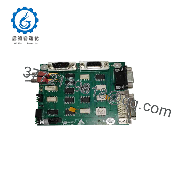
810-001489-016
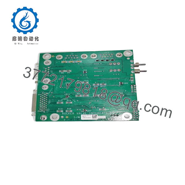
810-001489-016
Installation & Configuration Guide
Estimated replacement time: 30–60 minutes for an experienced semiconductor-equipment technician, excluding tool qualification.
Stage 1: Pre-Installation Preparation
⚠️ Safety First
- Place the Lam Research tool in its approved maintenance state.
- Stop wafer processing and complete the applicable chamber shutdown sequence.
- Apply the required electrical, pneumatic, vacuum, and process-gas isolation procedures.
- Verify hazardous energy has been removed.
- Follow the fab’s ESD and contamination-control procedures.
- Confirm the cabinet and board are at an approved service condition.
Tools Required
- ESD wrist strap
- Cleanroom gloves
- Phillips screwdriver
- Digital multimeter
- Connector labels
- Camera/smartphone
- Torque-controlled screwdriver where specified
- Current tool configuration backup
Data Backup
Before removing the existing board:
- Photograph the complete 810-001489-016 assembly.
- Record the part number and revision.
- Photograph all connectors.
- Record the board’s cabinet/rack location.
- Photograph cable routing.
- Record active tool alarms.
- Save the current equipment configuration where the tool permits it.
⚠️ Do not rely on memory for connector locations. Photograph the original board before disconnecting anything.
Stage 2: Removing the Old Module
- Confirm the tool is in the approved maintenance state.
- Verify electrical isolation.
- Label each connector before removal.
- Disconnect cables by the connector body rather than pulling on wires.
- Release the PCB mounting hardware.
- Remove the board straight from its mounting position.
- Place the removed PCB in an ESD-safe bag.
- Inspect the mounting area and connectors.
Check for:
- Bent connector contacts
- Contamination
- Corrosion
- Heat discoloration
- Damaged locking mechanisms
- Loose terminals
- Cable insulation damage
Estimated time: 10–20 minutes.
Stage 3: Installing the New Module
- Verify the replacement marking is 810-001489-016.
- Compare the PCB layout against the removed assembly.
- Confirm connector positions before installation.
- Wear the ESD wrist strap.
- Seat the board without forcing connectors.
- Secure the PCB using the original mounting hardware.
- Reconnect each cable according to the photographs.
- Confirm connector locks are fully engaged.
- Verify grounding/bonding connections where applicable.
Configuration Clone
If the original board contains configurable links, jumpers, or switches:
- Photograph their original positions.
- Replicate the exact configuration.
- Do not assume factory defaults match the installed tool.
- Verify any address or valve-selection settings against the tool documentation.
Self-Checklist
- Exact 810-001489-016 verified
- Board revision recorded
- Correct cabinet/rack location confirmed
- Connector positions matched
- All cables secured
- Mounting hardware secured
- ESD precautions maintained
- Original configuration documented
Stage 4: Power-On & Testing
- Perform a visual inspection before energizing the tool.
- Check for misplaced cables or foreign objects.
- Restore power according to the Lam Research maintenance procedure.
- Observe the board’s diagnostic LED.
- Check tool controller diagnostics.
- Command the applicable rocker valve through the approved service interface.
- Verify valve actuation.
- Verify valve-open/closed status feedback.
- Check for valve-control or interlock alarms.
- Confirm all affected valves respond correctly.
- Perform the equipment-specific functional test.
- Complete chamber/tool qualification before production release.
⚠️ Do not validate the replacement solely by confirming that the PCB powers up. The important acceptance test is correct command, feedback, interlock behavior, and tool-level operation.
Frequently Asked Questions (FAQ)
1. What is Lam Research 810-001489-016?
It is a Lam Research Rocker Valve Interface Board used in semiconductor processing equipment. Several independent parts listings identify the exact part number with this function.
2. Is 810-001489-016 a PLC I/O module?
Not in the conventional Siemens/Rockwell sense. It is a tool-specific interface PCB. One secondary source describes it as having 16 digital output connections for rocker-valve control, but the exact electrical architecture should be confirmed from Lam Research documentation for the target tool.
3. What equipment uses this board?
Listings associate 810-001489-016 with Lam Research semiconductor equipment, including rocker-valve systems and CMP-related equipment. The exact compatible tool models are not consistently documented in public sources, so the target equipment model should be confirmed before ordering.
4. Can I substitute 810-001489-002?
Do not assume that it is a direct replacement. A current aftermarket listing specifically states that the suffix variants can have different circuit and connector assignments. Match the complete 810-001489-016 number unless the applicable Lam Research documentation confirms an approved substitution.
5. Is 810-001489-016 obsolete?
It appears to be a legacy semiconductor-equipment spare, and new OEM inventory is limited in the secondary market. However, I did not find a public Lam Research lifecycle notice that establishes an official end-of-life date. Current listings show new, used, and parts-condition examples.
6. What condition is available?
Condition varies substantially by supplier. Current listings include new, used, and parts/as-is units. One marketplace listing explicitly identifies a used board with a three-month warranty, while another lists a parts-condition unit with no warranty.
For production equipment, specify New Original/New Surplus or Refurbished Tested rather than accepting an unspecified used board.
7. What should I verify before purchasing?
Provide the supplier with:
- Exact part number: 810-001489-016
- Board revision
- Photos of front and rear
- Connector photographs
- Lam Research tool model
- Cabinet/rack position
- Existing board condition
- Required condition of replacement
- Required warranty
- Functional-test requirements
There are conflicting online descriptions for this part, including an unrelated chamber-liner listing. I would therefore prioritize the physical PCB identification, installed-tool BOM, and Lam Research documentation over generic reseller specifications.
If you have a photo of the actual 810-001489-016 nameplate or PCB, it would help verify the revision and physical configuration before procurement.



