
 WhatsApp: +86 16626708626
 Email:
  Phone: +86 16626708626
Description
3. Key Technical Specifications
| Parameter | Specification / Value |
|---|---|
| Manufacturer | Lam Research |
| Part Number | 810-072903-014 |
| Revision Level | Revision D (Rev D) |
| Board Function | LonWorks PIO (Parallel Input/Output) Module |
| Network Protocol | Echelon LonWorks Bus Communication Standard |
| System Architecture | Lam Research Alliance, Kiyo, Vector, or 2300 Platform |
| User Interface | Onboard LCD / Status Indicator |
| Form Factor | Rack-mount card enclosure / Proprietary Card Slot |
| Operating Environment | Class 10/100 Cleanroom Tool Bay (18°C to 24°C) |
| Storage / ESD | Sealed in Anti-Static Shielding Bag |
4. Product Introduction & Value Proposition
The Lam Research 810-072903-014 is a specialized LonWorks Parallel Input/Output (PIO) control module engineered for high-precision semiconductor manufacturing tools. Built around the LonWorks distributed control protocol, this board acts as an essential local node—converting, processing, and routing real-time digital signals between the main tool controller workstation and various chamber actuators, mass flow controllers, vacuum interlocks, and sensor arrays.
Maintaining active stock of this PIO board is critical for fab maintenance teams. A failure in a LonWorks communication node halts tool communications, immediately triggering critical interlock alarms and taking the wafer processing chamber offline. Obtaining legacy or high-demand OEM boards directly during supply chain delays can lead to extended tool downtime, costing thousands of dollars per hour in lost wafer throughput. Sourcing genuine tested hardware ensures seamless plug-and-play network integration, preserving factory signal integrity and wafer processing yields.

810-072903-014
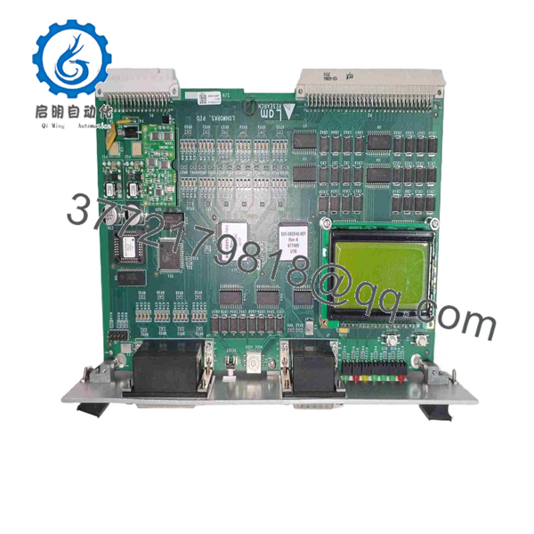
810-072903-014
5. Step-by-Step Installation & Maintenance Guide
Stage 1: Safety & Isolation
- Disconnect main power feeds to the tool control cabinet and enforce standard Lock-Out/Tag-Out (LOTO) procedures.
- Put on a cleanroom-rated anti-static smock, conductive footwear, and a properly grounded ESD wrist strap before handling the circuit card.
- Inspect the replacement board for physical damage and verify that onboard jumper blocks match your target tool slot configuration.
Stage 2: Removal of Existing Module
- Loosen top and bottom panel thumb screws on the active card slot.
- Squeeze or pull the card ejector handles simultaneously to unseat the module from the LonWorks backplane pins.
- Slide the board straight out along the guide rails and place it immediately into an ESD shielding bag.
Stage 3: Physical Installation
- Carefully align the replacement 810-072903-014 board with the enclosure guide channels.
- Push the module inward firmly until the ejector levers contact the frame, then lock the handles inward to fully engage the rear pin connectors.
- Tighten the retaining panel screws to guarantee proper grounding.
Stage 4: Boot & Diagnostic Verification
- Re-energize cabinet power and observe the onboard LCD status display / diagnostic LEDs.
J316Gallery
- Confirm the board establishes connection on the LonWorks bus without reporting communication faults to the main software console.
- Run standard software I/O loop diagnostics to verify signal responses across connected chamber subsystems.
1
Safety Setup
LOTO & ESD prep
1.Safety Setup:LOTO & ESD prep.
Power down cabinet systems using Lock-Out/Tag-Out procedures. Attach a grounded ESD wrist strap and verify jumper settings on the replacement card.
2
Board Removal
Unseat & extract
2.Board Removal:Unseat & extract.
Loosen retaining screws, disengage card ejector levers simultaneously to disconnect from the backplane, and pull out the old board.
3
Module Installation
Align & lock
3.Module Installation:Align & lock.
Slide the 810-072903-014 card along the guide rails. Lock the ejector levers to seat the backplane pins firmly, then secure panel fasteners.
4
System Diagnostics
LonWorks bus test
4.System Diagnostics:LonWorks bus test.
Power up the tool rack. Verify the onboard LCD/LED diagnostics pass self-test and confirm communication with the tool controller.
6. Frequently Asked Questions (FAQ)
Q: What is the main function of the Lam Research 810-072903-014 board? A: It functions as a LonWorks Parallel Input/Output (PIO) controller board that bridges high-speed system commands to individual sensor and valve sub-assemblies inside the wafer tool.
J316Gallery
Q: Are hardware jumpers required to be configured before powering on? A: Yes, address and bus termination jumpers must be matched exactly to the specific slot and chamber configuration of the card being replaced.
Q: Can this board be hot-swapped while the card rack is powered on? A: No. Replacing boards in an energized rack can cause electrical arc damage to edge contacts, disrupt active LonWorks communications, or damage sensitive transceiver components. Power down the card cage before installation.



