
 WhatsApp: +86 16626708626
 Email:
  Phone: +86 16626708626
Description
Key Technical Specifications
- Manufacturer: LAM Research
- Part Number: 810-073479-215
- Associated Part Number: 710-073479-215
- Board Identification: JTS MSTG & OPTIMUS GB MB
- Product Category: Motherboard PCB / circuit board assembly
- Application: LAM Research semiconductor-processing equipment
- Board Revision: Reported examples include Rev C and Rev D
- Electrical Rating: Not confirmed from reliable OEM documentation
- Communication Interface: Not confirmed for this exact board
- Firmware Version: Not confirmed
- Dimensions: Not confirmed
- Weight: Not confirmed
- Installation Position: Equipment-specific; verify the original board location before replacement
Important identification note: Online listings consistently associate this part number with the JTS MSTG & OPTIMUS GB motherboard, but some third-party pages assign unrelated functions and specifications to the same number. Those conflicting specifications should not be used for procurement or installation decisions.
Product Introduction
The LAM Research 810-073479-215 is identified in available spare-parts records as a JTS MSTG & OPTIMUS GB motherboard PCB used in LAM Research semiconductor equipment. The associated 710-073479-215 number also appears in equipment-parts listings.
This is a board-level replacement item rather than a generic PLC module. Revision, connector configuration, board markings, and equipment compatibility should be checked against the installed PCB before purchase. Historical listings specifically identify Rev C and Rev D examples, so revision control matters.
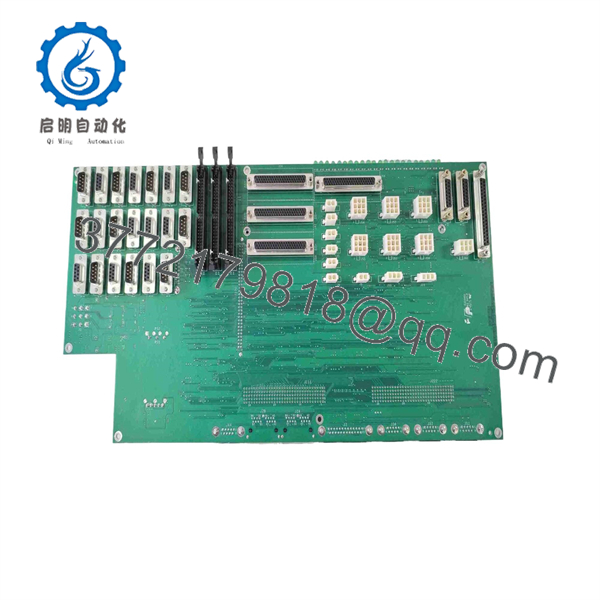
810-073479-215
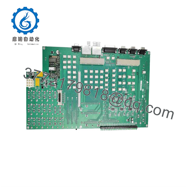
810-073479-215
Installation & Configuration Guide
Stage 1: Pre-Installation Preparation
Estimated time: 5–10 minutes
⚠️ Safety First: Follow the LAM Research equipment maintenance procedure for the specific tool. Place the equipment in the required safe state, isolate applicable power sources, and observe the site’s lockout/tagout procedure before removing the PCB.
Tools Required:
- ESD wrist strap and grounded ESD work surface
- Appropriate Phillips/flat-head screwdrivers
- Multimeter
- Wire or connector labels
- Smartphone or camera for configuration photographs
- Equipment service documentation
Data Backup:
- Record the installed board’s exact part number.
- Record the revision letter and all visible board identifiers.
- Photograph connector positions before disconnection.
- Photograph jumpers, DIP switches, and configuration links if present.
- Record cable routing and connector orientation.
- Retain the removed PCB until the replacement has passed functional testing.
⚠️ Do not assume that every 810-073479-215 board is electrically interchangeable. Available market records show different board revisions, including Rev C and Rev D.
Stage 2: Removing the Old Module
Estimated time: 5 minutes
- Confirm that the equipment has reached the required maintenance state.
- Remove the applicable protective cover or access panel.
- Photograph every connector before disconnecting it.
- Label connectors where there is any possibility of confusion.
- Release the PCB retaining hardware.
- Disconnect the board without pulling on individual wires or cable conductors.
- Remove the PCB straight from its mounting position where applicable.
- Inspect connectors, mating contacts, standoffs, and the backplane for contamination or physical damage.
⚠️ Keep the original board. If the replacement fails to initialize, the original PCB provides the reference for connector position, revision, jumpers, and physical configuration.
Stage 3: Installing the New Module
Estimated time: 5–10 minutes
- Confirm that the replacement is marked 810-073479-215.
- Compare the board revision and connector arrangement with the removed PCB.
- Put on the ESD wrist strap before handling the PCB.
- Inspect the board for bent pins, damaged connectors, corrosion, or shipping damage.
- Clone the original physical configuration where applicable, including jumpers, DIP switches, and termination settings.
- Install the PCB in the original mounting position.
- Secure the retaining hardware without excessive force.
- Reconnect each cable using the photographs and labels made during removal.
- Confirm that every connector is fully seated.
Self-Checklist:
- Part number verified
- Revision verified
- Board orientation correct
- Jumpers/DIPs matched where applicable
- Connectors fully seated
- Mounting hardware secured
- No cable trapped or pinched
Stage 4: Power-On & Testing
Estimated time: 10–15 minutes
- Inspect the installation for loose hardware and misplaced tools.
- Verify that no connector is partially engaged.
- Restore power according to the equipment service procedure.
- Observe the board and equipment status indicators.
- Check for abnormal alarms or initialization faults.
- Verify communication between the affected subsystem and the equipment controller.
- Run the applicable equipment diagnostic or service test.
- Confirm normal operation before returning the tool to production.
⚠️ Do not troubleshoot from the part number alone. The available public information does not establish the exact firmware, voltage rails, pinout, or communication architecture for this PCB. Use the LAM Research equipment-specific service documentation for those parameters.
Frequently Asked Questions (FAQ)
Can I use any 810-073479-215 board as a direct replacement?
Not automatically. The part number is strongly associated with the JTS MSTG & OPTIMUS GB motherboard, but available listings show multiple revisions. Match the complete board marking, revision, connectors, and equipment configuration before installation.
Is 710-073479-215 the same part?
It appears as an associated number with 810-073479-215 in multiple spare-parts records. However, do not treat the two numbers as interchangeable without confirming the equipment documentation or the physical board labeling.
Is 810-073479-215 obsolete?
The part is encountered primarily through the industrial semiconductor-equipment spare-parts market rather than conventional current-production automation distribution. Current OEM lifecycle status was not confirmed from an official LAM Research source, so procurement should be handled as a legacy-equipment spare until OEM status is verified.
Is this board genuinely new?
Condition varies by supplier. One current listing identifies the part as Used, while historical listings include tested-working and different revision descriptions. Do not assume “in stock” means factory-new. Request photographs of the actual board, including its P/N and revision marking, before purchase.
Can I hot-swap the 810-073479-215?
Do not assume hot-swapping is permitted. This is a board-level component associated with LAM Research semiconductor equipment, and the public information reviewed does not establish a hot-swap procedure. Follow the applicable LAM Research service procedure and remove power when required.
Will I lose equipment configuration when replacing the motherboard?
Potentially. The available sources do not establish whether configuration, firmware, or other system-specific data is retained independently of this board. Record the original board configuration before removal and follow the equipment’s approved backup and restoration procedure.
Why should I verify the revision before ordering?
Because 810-073479-215 has been listed in different revisions, including Rev C and Rev D. A visually similar board with a different revision may not have the same firmware, component population, or equipment compatibility.



