WhatsApp: +86 16626708626
 Email:
 Phone: +86 16626708626
Description
Key Technical Specifications
- Supply Voltage: 24 VDC
- Power Consumption: approximately 10 VA
- Display: text-oriented display (LCD class; verify display type against the 034.11JD configuration)
- Input Device: membrane keyboard (overlay customizable to application; replacement overlays available from aftermarket suppliers)
- PLC Communication: serial point-to-point via Lauer adapter cable; PLC-specific operating software (PCS 91.nn driver series) loaded in the PLC user program
- Supported PLCs: primarily Siemens SIMATIC S5 family; other controllers depending on the 034.11JD driver configuration — verify before ordering
- Configuration Software: PCSPro / PCSPro Plus / PCSPro Win (Lauer PC tools)
- Data Exchange: status-bit and data-area transfer between PLC data block and panel
- Mounting: panel / console cutout mounting, industrial enclosure class
- Manufacturer: Systeme Lauer GmbH & Co. KG, Kelterstr. 59, 72669 Unterensingen, Germany
- Status: Discontinued by manufacturer; sold as new surplus, refurbished, or via repair
- Weight/Dimensions: compact text-panel format (verify exact cutout dimensions against the Lauer PCS 009 manual before machining a new enclosure)
⚠️ Public documentation for the exact 034.11JD order code is thin. Verify display type, keypad layout, and PLC driver against the physical label and the PCS 009 manual before committing — Lauer built dozens of configuration variants under one model family.
Product Introduction
The Lauer PCS00903411JD is a member of the PCS 009 family of text-based operator panels from Systeme Lauer, Germany. It connects serially to a PLC — historically most often Siemens SIMATIC S5 — and lets operators view process data and enter setpoints through function keys and a text display. Typical installations: machine control consoles, packaging and production lines, and legacy retrofit jobs where the PLC and panel were engineered as a pair in the 1990s–2000s.
These panels were engineered for one job: keep a legacy line running without re-engineering the control system. The PCS 009 exchanges data with a dedicated PLC data block using Lauer’s PCS 91.nn operating software, so a like-for-like swap preserves your PLC program untouched. That’s the entire value proposition. There is no sensible “upgrade” path that doesn’t involve rewriting the PLC-side communications, so if your line still runs on S5, a tested replacement panel is the pragmatic choice.
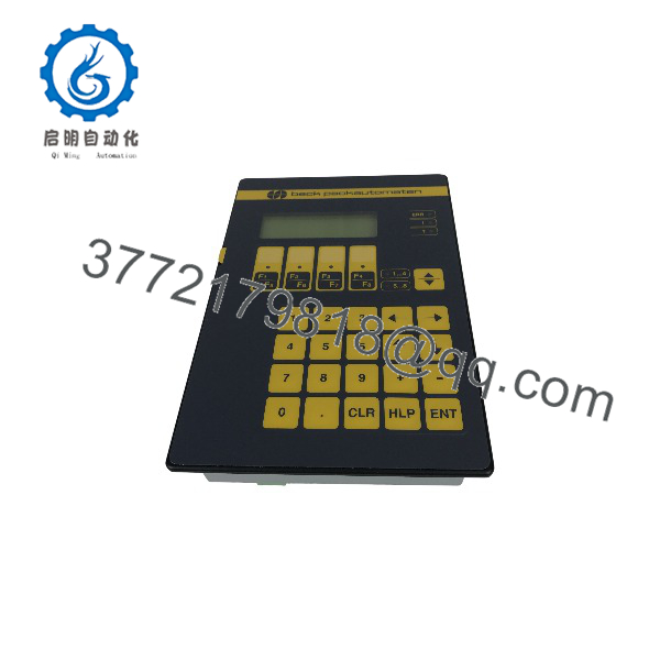
PCS00903411JD
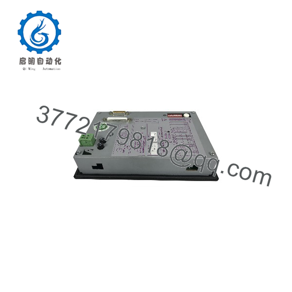
PCS00903411JD
Installation & Configuration Guide
Stage 1: Pre-Installation Preparation (Est. 15 minutes)
⚠️ Safety First: Notify operations of downtime. Machine to a safe state, lock out/tag out the panel supply (24 VDC), and confirm the PLC interface is de-energized.
- Tools Required: ESD strap, small flat and PH screwdrivers, multimeter, wire labels, smartphone for photos, panel-cutout template.
- Configuration Match Check (Critical): Photograph the old panel’s nameplate. The PCS009 order suffix (034.11JD) encodes the display and driver configuration — a different PCS 009 variant may not talk to your PLC. Confirm the replacement matches before you remove anything.
- Data Backup: Document the serial adapter cable routing (panel side and PLC side). Photograph terminal wiring. If the PLC-side PCS 91.nn driver software version is known, write it down — the Lauer manual warns communication is only guaranteed within matched driver/start-behavior combinations.
- ⚠️ Cabling Check: Lauer panels connect via PLC-specific adapter cables. Never assume a standard serial cable will work — verify the exact cable part number against the PCS 009 manual for your PLC.
Stage 2: Removing the Old Panel (Est. 10 minutes)
- Disconnect 24 VDC supply and the serial cable at the panel terminals.
- Release the panel-mounting clips or bracket screws from inside the console.
- Push the panel out of the cutout from behind. Don’t pry the front bezel against the enclosure paint — these panels sit in gasketed cutouts and pry damage ruins the IP seal.
- Inspect the cutout gasket; replace if compressed or torn.
⚠️ Keep the old panel. Its nameplate, keypad overlay, and even its EEPROM contents can matter for commissioning or a repair exchange.
Stage 3: Installing the New Panel (Est. 10 minutes)
- ESD strap on before handling the panel.
- Verify the replacement’s order code (PCS00903411JD) and any revision marks against the old nameplate photo.
- Seat the new panel in the cutout, ensuring the gasket is evenly compressed, and secure the mounting clips evenly — alternate corner by corner. Uneven clamping warps the membrane keyboard and kills keys.
- Reconnect the serial adapter cable and 24 VDC per your photos. Double-check polarity — reversed 24 V is a common way to kill a text panel on first power-up.
Self-Checklist: [ ] Order code matches, [ ] Gasket seated, [ ] Clips tightened evenly, [ ] 24 V polarity verified, [ ] Serial cable to correct PLC port.
Stage 4: Power-On & Testing (Est. 15 minutes)
- Power the panel alone first: confirm display backlight and any power-up/self-test indication.
- Put the PLC in a state where the panel exchange is active (many Lauer drivers only start the transfer when the PLC program initializes the data block).
- Verify data display: process values on screen should match actual PLC data-block values.
- Test every function key and the full keypad — membrane keyboards are the most common failure point on panels of this age, and a partially dead membrane needs to be caught now, not in production.
- Run a full shift-cycle dry run before releasing the machine.
⚠️ Troubleshooting Note: If the display powers up but shows no data, the fault is almost always the PLC-side driver or the serial cable — check the PCS 91.nn software in the PLC and the adapter cable type before condemning the panel. If the panel shows garbage characters, suspect a baud/driver mismatch. If keys work intermittently, check mounting-clip torque and overlay condition.
Frequently Asked Questions (FAQ)
Q1: Is this panel still manufactured?
No. Systeme Lauer discontinued the PCS 009 family years ago, and the PCS line overall has faded with its biggest consumer — Siemens S5 PLCs. The panel is available only as new surplus, refurbished, or via repair. Don’t plan a new machine design around it; plan line-sustaining spares strategy around it.
Q2: What exactly does the “034.11JD” suffix mean?
It’s the Lauer order/configuration code for this specific PCS 009 build — display type, keypad layout, and PLC driver configuration. The PCS 009 name covers many variants, and they are not all interchangeable. Honestly, public documentation mapping this exact suffix is scarce — that’s why we photograph the nameplate of every unit and ask you to match against your installed panel before we ship. If you’re unsure, send us your old panel’s full label photo and we’ll confirm the match.
Q3: Can I replace it with a modern HMI instead?
You can, but it’s not a swap — it’s a project. A modern panel (WAGO/Beijer, Weintek, Siemens) has no built-in driver for the Lauer data-block protocol, so someone has to reverse-engineer the serial exchange and rewrite the PLC-side logic, or migrate the PLC too. For a healthy S5 line with a failing panel, a tested PCS 009 replacement is hours of downtime. A modern-HMI migration is days of engineering plus revalidation. I’ve done both; only do the migration when the panel shortage forces it or the line is being rebuilt anyway.
Q4: Will my PLC program still work with the replacement panel?
Yes — that’s the point of a like-for-like swap. The PCS 009 communicates through the PCS 91.nn driver software in your PLC’s user program via a serial adapter cable; the panel itself holds no user logic you need to migrate. Two caveats: the replacement must be the same configuration variant (or at minimum the same driver type), and if anyone re-flashed or modified the PLC-side driver, re-test the exchange after installation. If you have the PCSPro project file, keep it — configuration tools for these panels are getting hard to source.
Q5: What condition are these panels in, and why is your price below original list?
Stock on this model is a mix: new-surplus units (never installed, may show shelf wear on the membrane), and refurbished units with new overlays where the original membrane was worn. Every unit is powered up on a 24 V bench supply, display and keypad tested, and the serial interface checked where we have the mating driver hardware. Prices sit below original list because the product is discontinued and trades on the surplus market. We state the condition of the exact unit on the listing — New Surplus and Refurbished (tested) are never mixed. Membrane condition matters most on these panels; ask for close-up photos of the keypad overlay before buying anywhere.
Q6: Can I replace just the membrane keyboard?
Sometimes, yes — aftermarket suppliers offer replacement membrane overlays for common PCS 009 variants, and a worn keypad with healthy electronics is worth repairing. Match the overlay to your exact keypad layout; wrong-layout overlays turn a simple fix into a labeling mess. If the display or the board is failing, the more economical route is a complete replacement panel from stock. We can advise case by case if you send photos of the panel and its nameplate.
Q7: What’s the biggest installation mistake with these panels?
Two, from field experience. First: reversed or miswired 24 V supply — these panels tolerate very little abuse on power input, and a polarity mistake can end the panel before it ever boots. Check with a multimeter before connecting. Second: uneven mounting-clip torque, which warps the membrane and produces intermittent keys that get misdiagnosed as a “bad panel” and trigger a needless replacement cycle. Tighten the clips evenly, corner by corner, and you’ll avoid 90% of the callbacks.