WhatsApp: +86 16626708626
 Email:
 Phone: +86 16626708626
Description
Key Technical Specifications
The following values come from Lauer’s PCSmaxi manual covering PCS 9000 and PCS 9100. Verify the actual unit’s label, installed modules, and hardware revision before installation.
| Parameter | Value |
|---|---|
| Supply Voltage | 24 V DC ±20%; reverse-polarity protected |
| Current Consumption | Average 650 mA without cassette at 24 V DC; average 1.15 A with four cassettes at 24 V DC |
| Documented Inrush | 4 A with four cassettes at 32 V DC, as stated in the manual |
| Display | Active LCD; full graphics; 640 × 480 pixels |
| Operator Keys | 16 function keys with three indicator LEDs each; 10 additional vertical soft keys; numeric and control keys |
| Expansion Architecture | Four rear module slots; at least one suitable PLC interface module required |
| Internal Memory | 256 KB Page ROM; approximately 80 KB allocated to firmware |
| Programming Interface | RS-232; 38.4 kbaud; 25-pin female connector |
| Auxiliary Interfaces | RS-232 printer port: 300–19,200 baud; RS-422 external keyboard port: 130 kbaud |
| Dimensions and Weight | External: 410 × 266 mm; depth without connectors: 75 mm; approximately 3.7 kg, or 4.7 kg with four cassettes |
| Enclosure Protection | Front: IP65 when installed; rear: IP20 |
| Environment and Fuse | Operation: 0–45 °C; storage: −20 to +60 °C; 3.15 A miniature slow-blow fuse |
All table values are from the Lauer manual. External dimensions are not the panel cutout dimensions; verify the mounting drawing separately.
❗ Warning: The manual lists a 32 V inrush test condition, but its specified operating supply remains 24 V DC ±20%, or 19.2–28.8 V DC. Do not treat 32 V as an approved continuous supply voltage.
Product Introduction
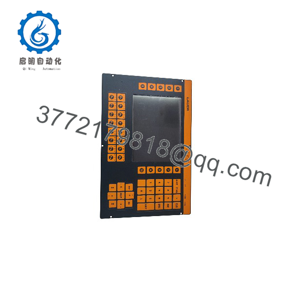
The LAUER PCS9100 is a modular graphic operator panel for PLC-connected machine operation, process visualization, messages, and recipe handling. Its 640 × 480 LCD combines F1–F16 function keys with ten additional vertical soft keys for application-defined operator actions.
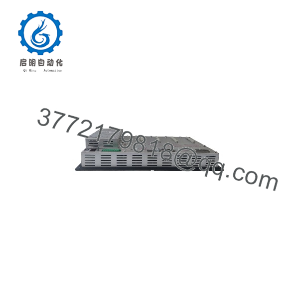
Four rear module slots accommodate communication and application options. It is a replacement candidate for existing PCSmaxi installations only after verifying the interface module, project, cable pinout, mounting dimensions, and machine-specific configuration.
Troubleshooting Quick Reference
| Symptom | Possible Cause | Relevance to this Part | Quick Check Method | Recommendation |
|---|---|---|---|---|
| No display or status activity | Missing supply, voltage drop, rear switch off, fuse, or internal power fault | External supply checks first | Measure DC voltage between Port 1 pin 2 (+24 V) and pin 1 (0 V), including during startup; verify rear power switch | Correct supply issues before replacing the panel |
| Supply collapses during startup | Insufficient PSU capacity, wiring resistance, or internal fault | Supply and panel both require checking | Capture minimum startup voltage at the panel terminals; compare fitted-module load with PSU capability | Test with a suitable current-limited supply; do not size from unloaded current alone |
| Display blank but other activity remains | Display assembly, connection, or internal electronics problem | Display fault possible | Check whether COM/SYS activity continues; document the screen condition and test on a controlled bench | Request display-level diagnosis rather than assuming the complete panel is defective |
| COM indicator steady | Communication not yet established | Configuration or connection first | Identify the installed PLC interface module; compare cable and driver configuration with the original system | Verify the interface and PLC before replacement |
| COM indicator flashing | Previously established communication interrupted | Link or controller issue possible | Check PLC state, connector security, cable continuity with power removed, and module configuration | Restore the link before condemning the HMI |
| SYS indicates no program | Missing project or empty cassette | Program/module issue directly relevant | Check project availability and fitted cassette identification; compare with the removed panel | Restore the verified project or correct module; do not assume hardware failure |
| Keys do not affect the machine | Access restrictions, communication failure, project mapping, or key damage | HMI or application issue possible | In a safe test state, monitor DW04 for F1–F16 and DW05 for T1–T10 in the configured PLC exchange area | Separate key recognition from PLC logic and permissions |
| Menus or messages are missing | PLC-controlled transfer/display locks | Application-controlled behavior possible | Inspect configured DW13 transfer-lock and DW14 display-lock bits | Correct application state before replacing hardware |
Status meanings, terminal assignments, and diagnostic data-word functions follow Lauer’s manual. They are not failure-frequency claims.
If the fault remains, contact technical support with front/rear photos, complete labels, module identifiers, DIL-switch photos, measured supply voltage, PLC details, and COM/SYS behavior.
PCS9100
PCS9100
Frequently Asked Questions (FAQ)
Is the PCS9100 a touchscreen, and can a PCS9000 replace it?
The documented PCS9100 uses an LCD with physical operator keys. Do not advertise touchscreen operation without evidence for the specific unit. Lauer identifies F1–F16 function keys and ten additional vertical soft keys, T1–T10.
A PCS9000 is not automatically equivalent. The manual identifies T1–T10 and their PLC exchange word, DW05, as PCS9100-specific features. An application using those keys needs a replacement that preserves their functions or a reviewed application modification.
Likewise, a replacement membrane film or LCD assembly is not a complete PCS9100 operator panel. State the scope of supply clearly.
Will any PCS9100 communicate with my existing PLC?
Not without matching the installed interface hardware and configuration. Lauer states that an interface module is mandatory. The PCS 8010 provides serial interface options, but the installed module, selected driver, matching adapter cable, and PLC exchange area determine the working connection.
Before ordering, record:
- PLC manufacturer and exact CPU model.
- Installed interface module designation.
- Occupied rear slots and module order.
- Cable number and verified pinout.
- Driver/project identification.
- Existing communication settings.
RS-232, RS-422, and RS-485 identify electrical interfaces—not proof of Modbus, Profibus, or another application protocol. Do not add unsupported protocol claims.
Will the replacement retain my screens, recipes, and settings?
Do not assume a replacement arrives with the machine project. Lauer documents project creation with PCS 9092 and transfer through the programming interface. The panel’s memory and fitted cassettes are part of the application configuration.
Secure the original project files, driver information, available backups, and module records before removing the working panel. Record firmware information where accessible and confirm that the intended project and programming tools support the replacement.
No actual firmware revision was supplied. A revision-match guarantee would be unsupported. Also, do not assume that a generic Lauer programming package supports this model simply because it supports other PCS panels: the PCSmaxi manual specifically identifies PCS 9092.
What switch, connector, and power mistakes should I avoid?
Photograph the rear configuration before disconnecting anything.
- DIL configuration: The manual identifies four DIL inputs and operating modes that include forced programming. Document the original state and verify the intended mode before startup. Do not interpret these switches as generic node-address or baud-rate selectors.
- Connector selection: The programming and printer connections are both 25-pin RS-232 ports. Match the port label and wiring diagram—not just the connector shape.
- Power wiring: Port 1 pin 1 is 0 V; pin 2 is +24 V DC. Verify polarity and voltage at the panel before connection.
- Supply capacity: Include fitted-module demand and startup behavior. The manual lists 1.15 A average with four cassettes at 24 V DC. A 20% planning margin does not replace startup-current verification.
- Mechanical fit: Check the actual cutout, mounting holes, connector clearance, gasket, and module depth. The published 410 × 266 mm dimensions describe the exterior, not the required cutout.
Isolate panel power before replacement and use grounded ESD protection when handling electronics. Do not connect or remove modules on a powered assembly without an applicable OEM procedure.
Is it obsolete, new surplus, or available with a warranty?
The reviewed material establishes a legacy PCSmaxi platform, but it does not verify current OEM lifecycle classification or the offered unit’s condition.
Independent suppliers list PCS9100 repair or replacement services, including a machine-specific PCS9100-Dreistern listing. Their availability and warranty terms apply to their own offers—not automatically to another seller’s unit.
Require a written quotation stating:
- Complete label identification and any machine-specific designation.
- Actual stock quantity and committed dispatch date.
- Condition: New Original / New Surplus, Factory Sealed, used, or Refurbished (tested), supported by evidence.
- Included interface modules, cassettes, connectors, and mounting hardware.
- Display/keypad condition and disclosed repairs.
- Warranty duration, exclusions, and return procedure.
A lower price does not establish authenticity, condition, project compatibility, or remaining display life.
What inspection and testing should the supplier document?
Request a serial-linked acceptance report in this order. No actual-unit inspection or test results were supplied.
- Inbound inspection and traceability
Review available OEM packing lists, purchase records, and applicable customs documents. Cross-check labels and serial numbers. Inspect for corrosion, scratches, rework, discoloration, cracked overlays, damaged keys, connector defects, and gasket deterioration. Audit modules, accessories, manuals, and certificates. Check security markings only where the production version actually used them. - Live functional testing
Identify the 24 V DC supply, installed modules, test PLC or simulator, programming tools, cables, and calibrated measurement instruments. Record startup voltage/current, boot behavior, display uniformity, COM/SYS indications, and every operator key. Demonstrate PLC reads and writes with a disclosed test project. Test fitted options within their documented limits. If acceptance requires a run exceeding 24 hours, log duration, supply conditions, display/key operation, communications, and temperature observations. - Electrical parameter testing
Perform appropriate documented low-voltage checks and grounding checks where applicable. Do not apply a blanket 500 V megohmmeter test across power inputs, serial ports, or internal electronics. The reviewed manual does not establish that as an approved field acceptance procedure. Require an applicable OEM method before insulation-resistance or hipot testing. - Firmware and configuration verification
Record accessible firmware information, project/driver identification, module designations, DIL settings, and programming configuration. Preserve photographs and backups. Verify battery requirements from the actual assembly and applicable documentation: the archived manual contains differing battery markings, so do not select a replacement from a generic voltage claim alone. - Final QC and packaging
Require inspector sign-off, a dated serial-linked report, ESD-safe packaging, display-face protection, connector protection, cushioning, and a rigid corrugated box. Apply a dated QC label. Request actual-unit test photos and videos where available; claim documented functionality only when those records support it.