
 WhatsApp: +86 16626708626
 Email:
  Phone: +86 16626708626
Description
Key Technical Specifications
| Parameter | Value |
|---|---|
| Manufacturer | LEM |
| Alternate Identification | LC1000-SSP7 / LC-1000-S/SP7 |
| Product Type | Closed-loop current transducer |
| Measurement Principle | Hall effect closed-loop compensation |
| Primary Current Range | ±1000 A |
| Conversion Ratio | 1:4000 |
| Supply Voltage | ±24 VDC |
| Output Type | Analog current/voltage output (configuration dependent) |
| Load Resistance | 25 Ω |
| Isolation Type | Galvanic isolation between primary and secondary circuits |
| Application Frequency | DC, AC, and pulsed current measurement |
| Response Time | Microsecond range, application dependent |
| Mounting | Industrial panel/module mounting |
| Weight | Approximately 1.68 lb (0.76 kg) |
| Operating Environment | Industrial control cabinet installation |
The LEM LC1000-S/SP7 is listed as a current transducer module with ±24 V supply requirements, 25 Ω load resistance, and a 1:4000 current ratio.
Product Introduction
The LEM LC1000-S/SP7 is a closed-loop current transducer designed for measuring high electrical currents in industrial power conversion and automation systems. It provides isolated current feedback for applications such as motor drives, power converters, and industrial electrical monitoring systems.
This sensor is often maintained as a spare component in legacy ABB and industrial drive systems. Replacement requires matching the current range, supply voltage, mechanical mounting, connector arrangement, and calibration characteristics.
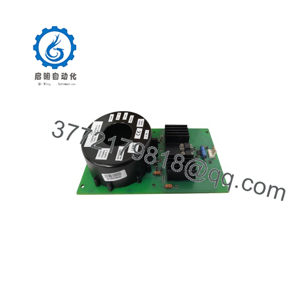
LC1000-S/SP7
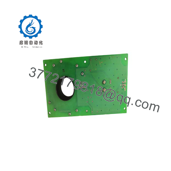
LC1000-S/SP7
Installation & Configuration Guide
Stage 1: Pre-Installation Preparation — 10 minutes
⚠️ Safety First
- Notify operations before working on the power conversion system.
- Place the equipment into a safe maintenance state.
- Apply lockout/tagout procedures.
- Isolate all high-current sources.
- Wait for DC bus discharge according to the equipment manual.
- Verify zero voltage with a properly rated multimeter.
Tools Required
- ESD wrist strap
- Insulated screwdriver set
- Digital multimeter
- Current measurement documentation
- Wire labels
- Smartphone for reference photos
Data Backup
- Record the complete LC1000-S/SP7 label.
- Photograph wiring and connector orientation.
- Document supply polarity.
- Record output signal wiring.
- Confirm the drive or converter model using the sensor.
⚠️ Important: Current transducers are not interchangeable by current rating alone. Verify ratio, output scaling, and supply requirements.
Stage 2: Removing the Old Module — 5–10 minutes
- Open the electrical cabinet.
- Confirm power isolation.
- Verify the high-current conductor is de-energized.
- Photograph the sensor installation direction.
- Label supply and output terminals.
- Disconnect secondary wiring carefully.
- Remove mounting hardware.
- Remove the transducer without stressing the primary conductor.
⚠️ Do not pull or rotate the primary conductor through the sensor opening. Mechanical stress can damage bus connections and insulation.
Stage 3: Installing the New Module — 10 minutes
- Wear ESD protection.
- Confirm replacement marking matches LC1000-S/SP7.
- Compare mechanical dimensions.
- Verify current direction marking.
Configuration Clone (Critical)
- Match current ratio.
- Match supply voltage polarity.
- Match output scaling.
- Match connector wiring.
- Confirm grounding/shielding arrangement.
- Install the sensor in the same orientation.
- Secure mounting hardware.
- Reconnect secondary terminals.
- Verify wiring against photographs.
Self-Checklist
- Correct LC1000-S/SP7 model verified
- Current direction confirmed
- Supply voltage checked
- Output wiring verified
- Mechanical mounting secured
Stage 4: Power-On & Testing — 15 minutes
- Perform a final wiring inspection.
- Restore control power first.
- Verify sensor supply voltage.
- Check output signal at zero current.
- Apply controlled load conditions.
- Compare measured feedback with system diagnostics.
- Verify drive/controller alarms remain clear.
⚠️ Troubleshooting Note
- Incorrect current feedback: Check sensor orientation and polarity.
- Output saturation: Verify current range and load resistance.
- No signal: Check ±24 VDC supply and secondary wiring.
- Unstable reading: Inspect shielding and grounding.
Frequently Asked Questions (FAQ)
Can I hot-swap the LEM LC1000-S/SP7?
No. A current transducer installed in a power circuit should be replaced only after isolating the electrical system. The primary conductor may carry hazardous current even when the control circuit appears inactive.
Is the /SP7 obsolete?
Yes. The /SP7 is listed as discontinued by the manufacturer. Availability normally comes from surplus inventory, repair channels, or tested replacement suppliers.
Is LC1000-SSP7 the same as /SP7?
In many industrial listings, LC1000-SSP7 is used as an alternate search name for /SP7. However, always verify the physical label and electrical specifications before replacement.
Can I replace it with another 1000 A current sensor?
Not automatically. The replacement must match the current ratio, output type, supply voltage, mechanical dimensions, and controller scaling parameters.
Will replacing the /SP7 require software changes?
Usually, the sensor itself does not contain application logic. However, the connected drive or controller may require verification of scaling parameters if the output characteristics differ.
Why is the /SP7 cheaper than a new OEM component?
Legacy industrial sensors are commonly sourced from discontinued equipment, surplus warehouses, and refurbishment programs. Price depends on condition: New Original, New Surplus, and Refurbished (tested) units should be evaluated separately.
What information should I provide when ordering /SP7?
Provide:
- Complete nameplate photo
- Existing sensor model
- Drive/converter model
- Supply voltage
- Output wiring photo
- Application current range
These details prevent installing a sensor with an incompatible ratio or output signal.



