
 WhatsApp: +86 16626708626
 Email:
  Phone: +86 16626708626
Description
| Parameter | Specification |
| Input Voltage | 12 to 24 VDC ±10% |
| Maximum Current Draw | 550 mA maximum (plus reader current) |
| Upstream Communication | RS-485 2-wire or 4-wire (up to 4,000 ft / 1,219 m) |
| Reader Supported Ports | 2 Ports (Wiegand Data1/Data0, Clock/Data, OSDP RS-485) |
| Reader Power Output | Regulated 12 VDC (125 mA max each) or pass-through VIN |
| General Purpose Inputs | 8 Supervised/Unsupervised (1k/1k Ω EOL standard) |
| Dedicated Alarm Inputs | 2 Unsupervised (Cabinet Tamper and Power Fault) |
| Relay Outputs | 6 Form-C relays, rated 5 A @ 28 VDC resistive |
| Card Formats Supported | Up to 16 distinct card formats (plus issue code support) |
| Operating Temperature | 32°F to 158°F (0°C to +70°C) |
| Operating Humidity | 0% to 95% RH non-condensing |
| Dimensions & Weight | 6.0″ W x 8.0″ L x 1.0″ H (152 x 203 x 25 mm); 11 oz (312 g) |
| Compliance Approvals | UL 294, UL 1076, ULC CSA-C22.2, CE, FCC Part 15, RoHS |
The LenelS2 LNL-1320 Dual Reader Interface (DRI) is an edge-level access control board designed to bridge up to two physical card readers, door hardware, and auxiliary alarm points directly to an Intelligent System Controller (ISC) via RS-485. Built for integration with LenelS2 OnGuard systems, it processes local decision-making for door contacts, Request-to-Exit (REX) sensors, and electric strike outputs.
The module supports legacy Wiegand and Clock/Data setups alongside modern bidirectional OSDP protocols with AES encryption on newer board revisions. Its hardware architecture allows up to 32 multidropped DRI modules on a single RS-485 port. Built-in offline access logic preserves facility access continuity if upstream controller communication drops.
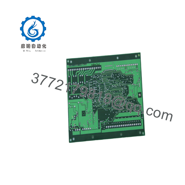
LNL-1320-S3B
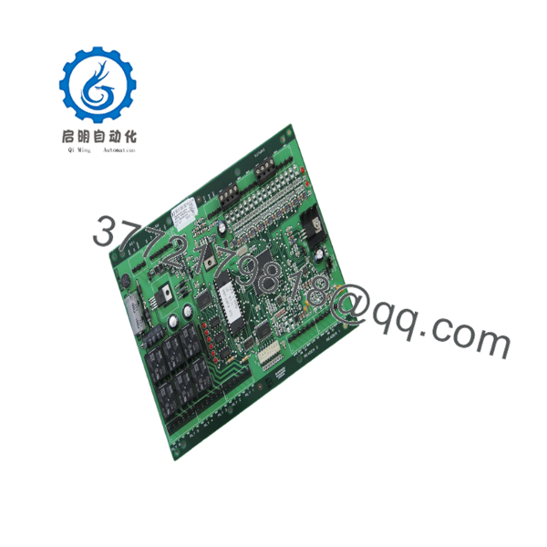
LNL-1320-S3B
Estimated Time: 20 to 30 minutes
Stage 1: Pre-Installation Preparation
- ⚠️ Safety First: Inform security operations that doors linked to the module will be offline. Place doors in a controlled, manual state. Isolate power from the panel branch circuit breaker. Wait 5 minutes to ensure full power discharge before touching internal terminals.
- Tools Required: ESD grounded wrist strap, PH1 precision screwdriver, Fluke multimeter, wire markers, wire stripper, smartphone for configuration recording.
- Data Backup: Photograph DIP switch positions (SW1/SW2), jumper block locations (J2, J3, J4), and exact terminal wiring terminations on TB1 through TB8.
Stage 2: Removing the Old Module
- Snap off the protective plastic cover.
- Label every wire bundle relative to terminal block tags (IN1–IN8, OUT1–OUT6, RS-485, Reader 1/2).
- Carefully unplug removable screw terminal blocks or loosen fixed screws to release field wiring without pulling on conductors.
- Unscrew mounting hardware or release snap tabs from the enclosure backplane. Pull the PCB out straight to prevent bending structural alignment pins.
- Inspect enclosure interior for copper strands, dust accumulation, or signs of voltage tracking.
Stage 3: Installing the New Module
- Wear a grounded ESD wrist strap before opening the static shield packaging. Match board revisions (Series 2 vs. Series 3) to ensure physical jumper layouts match site engineering standards.
- Configuration Clone (Crucial): Set the 8-position DIP switch on the replacement module to mirror the RS-485 node address and baud rate of the old unit. Configure termination jumpers (120 Ω) if this module is at the physical end of the RS-485 bus line.
- Mount the new PCB onto enclosure standoffs and fasten securely.
- Reconnect terminal blocks or wire individual leads into screw terminals according to labels. Torque terminals to 0.5 Nm (4.4 in-lbs).
- Self-Checklist: [ ] DIP switches match old PCB, [ ] RS-485 polarity verified (A/B), [ ] EOL resistors installed on supervised input channels.
Stage 4: Power-On & Testing
- Measure incoming power lines with a multimeter to verify 12–24 VDC output before terminating the primary power block.
- Apply power. Watch the boot sequence: Status LED A should flash rapidly while requesting/initializing system firmware.
- Confirm LED A transitions to a steady heartbeat blink once linked with the upstream ISC. LED R1 and R2 should flash when reader card transactions occur.
- Verify door strikes activate upon card swipes inside OnGuard hardware tree view.
- ⚠️ Troubleshooting Note: If LED A remains in a continuous rapid flash pattern, the unit is stuck waiting for a firmware download from the ISC. Verify RS-485 wiring polarity (A to A, B to B) and check that the assigned node address DIP switch isn’t duplicated on the channel.
Q: Can I hot-swap an LNL-1320 module while the panel power is live?
A: No. Replacing the LNL-1320 with power applied creates a risk of voltage spikes on the RS-485 data bus and reader power rails. Pulling or inserting live terminal blocks can ground active lines or short out 24 VDC directly to sensitive I/O lines, which can damage the replacement board or adjacent downstream units on the loop. Always isolate power at the distribution block before swapping modules.
Q: What is the main functional difference between LNL-1320 Series 2 and Series 3 boards?
A: Series 3 boards include expanded support for bidirectional OSDP (Open Supervised Device Protocol) readers with AES-128/256 encryption, biometric template download, and upgraded onboard memory handling. Series 3 is backward-compatible with Series 2 installations in terms of footprint and terminal locations, making it a drop-in replacement, though firmware updates on the head-end Intelligent System Controller (ISC) may be required to enable newer encryption functions.
Q: Will swapping out the LNL-1320 erase cardholder credentials or event history?
A: No. The LNL-1320 is an edge reader interface; cardholder database structures and transactional event logs are stored upstream on the Intelligent System Controller (e.g., LNL-2220 / LNL-3300) and within the OnGuard database server. Once the replacement board’s DIP address is set correctly and RS-485 comms establish, the host controller automatically pushes operational parameters and firmware down to the board.
Q: How do I select 12 VDC reader power if the main board supply input is 24 VDC?
A: The features an onboard voltage regulator. You can set the reader power selection jumpers (typically J2 for Reader Port 1, J3 for Reader Port 2) to the regulated 12 VDC position. This steps down incoming 24 VDC primary power to a regulated 12 VDC output (up to 125 mA per port) for standard readers. Leaving jumpers in pass-through mode will pass the full input voltage straight to the reader, which can destroy 12V-only card readers if 24 VDC is applied.
Q: Why are input channels showing constant alarm faults after replacing a unit?
A: This usually indicates an End-of-Line (EOL) resistor mismatch. The expects a standard 1k/1k Ω dual-resistor supervised circuit configuration by default. If the field wiring uses non-standard values (e.g., 4.7k Ω or 2.2k Ω) or unsupervised dry contacts, the software configuration in OnGuard must match the physical EOL setup. Also verify that wires were not swapped between the door contact and REX inputs during re-termination.
Q: How are your prices lower than OEM direct list price on factory sealed units?
A: We source new surplus inventory, bulk integration stock, and excess project hardware directly from verified commercial contractors and enterprise upgrade projects. Every item undergoes physical inspection and anti-counterfeit verification. You receive brand new OEM hardware backed by our standard 1-year replacement warranty without paying inflated factory list prices or dealing with multi-week lead times.



