
 WhatsApp: +86 16626708626
 Email:
  Phone: +86 16626708626
Description
Key Technical Specifications
| Parameter | EPL10200 |
|---|---|
| Manufacturer | Lenze |
| Model | EPL10200 / EPL-10200 |
| Product family | Drive PLC |
| Controller type | Compact programmable drive controller |
| Supply voltage | 24 VDC |
| Digital inputs | 8 |
| Digital outputs | 4 |
| Analog inputs | 3 |
| Analog output | 1 |
| System bus | CAN |
| CAN transmission | Up to 1 Mbit/s depending on network configuration |
| Programming software | Drive PLC Developer Studio (DDS) |
| Expansion interface | FIF interface / extension-board interface |
| Communication options | LECOM, INTERBUS, PROFIBUS-DP, CANopen/DeviceNet through compatible modules |
| Status | Legacy / discontinued |
The Lenze mounting documentation identifies the EPL10200 as a Drive PLC and shows its CAN system-bus connections, analog inputs, analog output, and optional FIF/AIF modules.
Lenze’s own documentation also confirms that EPL-10200 versions evolved through multiple software generations. For example, Lenze documents differences between V7.1 and V8.1 and between V8.1 and V8.2.
Product Introduction
The Lenze EPL10200 is a compact Drive PLC designed for machine-control applications where PLC logic is integrated closely with Lenze drive technology. The controller provides digital and analog I/O and uses the Lenze CAN-based system bus for communication with compatible drive-system components.
For legacy-machine maintenance, the software version is particularly important. Lenze documents functional differences between EPL-10200 software generations, so replacing the hardware without checking the existing project, firmware/software version, and connected communication modules can create compatibility problems.
Installation & Configuration Guide
1. Pre-Installation
- ⚠️ Remove the 24 VDC control supply and follow the machine’s lockout/tagout procedure.
- Record the existing EPL10200 hardware identification, software/firmware version, and connected option modules.
- Back up the PLC project before removing the original controller whenever the existing CPU is still accessible.
- Photograph the terminal wiring, CAN connections, and any installed FIF/AIF modules.
- Confirm whether the application uses EPZ extension boards or optional communication modules.
2. Remove the Existing PLC
- Verify that the controller and connected drive equipment are de-energized.
- Disconnect the 24 VDC supply and field wiring.
- Label CAN-H, CAN-L, signal common, and I/O wiring where required.
- Remove the controller from its mounting arrangement without damaging the connector interfaces.
- Preserve any compatible option modules that must be transferred to the replacement.
3. Install the Replacement
- Compare the replacement EPL10200 with the removed unit, including hardware revision and connector arrangement.
- Install the controller in the original position.
- Reconnect the 24 VDC supply with correct polarity.
- Reconnect I/O and CAN wiring according to the approved Lenze wiring diagram.
- Reinstall compatible communication or function modules in their specified interfaces.
- ⚠️ Check CAN termination and network topology before powering the system.
4. Power-On and Testing
- Apply 24 VDC while keeping machine motion disabled.
- Establish communication with the PLC using the applicable Lenze engineering/service interface.
- Load the verified PLC project using Drive PLC Developer Studio (DDS) where required. The commissioning documentation specifically identifies DDS as the software used to load the required project.
- Confirm PLC program status and diagnostic messages.
- Test digital inputs and outputs individually.
- Check analog input/output scaling against the machine documentation.
- Verify CAN communication with connected Lenze devices.
- Confirm start/stop/reset behavior and machine interlocks before enabling automatic operation.
Important software consideration: Lenze documents upward compatibility between certain software versions, but also warns that transferring parameter sets from higher software versions to lower versions can cause errors because newer versions contain additional functions.
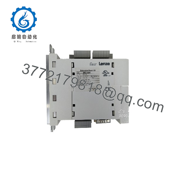
EPL10200
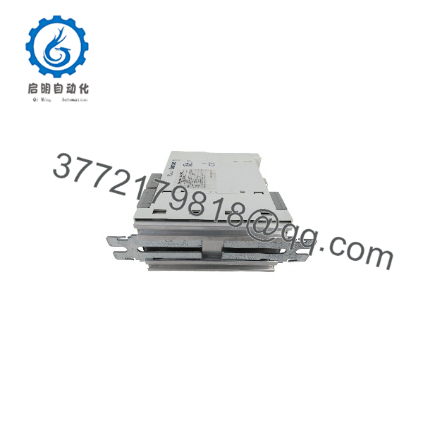
EPL10200
Frequently Asked Questions (FAQ)
Q1. What is the Lenze ?
The is a Lenze Drive PLC, intended for programmable machine and drive-control applications. Lenze documentation identifies the type designation as .
Q2. What voltage does the use?
The commonly documented supply is 24 VDC. A replacement should nevertheless be checked against the installed unit’s nameplate and electrical drawings before energization.
Q3. What I/O does the provide?
A current secondary listing specifies 8 digital inputs, 4 digital outputs, 3 analog inputs, and 1 analog output. The Lenze mounting documentation also shows dedicated analog input/output and CAN connections.
Q4. What programming software is used with ?
Lenze’s commissioning documentation identifies Drive PLC Developer Studio (DDS) for loading the required PLC project.
Q5. Does the support CAN?
Yes. The uses the Lenze system bus based on CAN, and the documentation provides CAN wiring and communication information for the Drive PLC.
Q6. Can an be replaced by another Lenze PLC?
Not as a generic drop-in replacement. The existing PLC program, I/O configuration, CAN network, optional modules, and software version must be checked. software generations also have documented functional differences.
Q7. Is the Lenze obsolete?
It is a legacy/discontinued platform. Current secondary-market listings identify it as discontinued, while Lenze’s technical documentation continues to provide information for the EPL-10200 and its historical software versions.
Procurement note: For an replacement, provide the complete model designation, hardware revision, software/firmware version, existing option modules, and a photograph of the original nameplate. For a running production machine, preserving the original PLC project and verifying the CAN configuration should be treated as part of the replacement procedure, not as an optional commissioning step.



