WhatsApp: +86 16626708626
 Email:
 Phone: +86 16626708626
Description
Core Product Summary
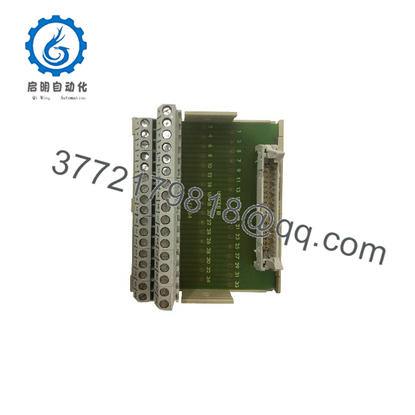
The Lütze UBE-FL/34 (also cataloged as UBE-FL34 or UBE-FL/34 M) is a 34-pole passive interface breakout module engineered to bridge flat ribbon cable connections with discrete terminal wiring in industrial control cabinets. It converts a standard 34-position ribbon cable header into a row of screw terminals, simplifying connections between PLC I/O cards, controllers, and field fieldbus devices.
Designed for mounting on standard TS35 DIN rails, the UBE-FL/34 consolidates wiring within automation panels, eliminating the need for point-to-point manual solder connections or custom wiring harnesses. Its compact design includes clear pin-to-terminal marking and electrical separation between adjacent channels to preserve signal integrity across low-voltage control lines.
Key Technical Specifications
| Parameter | Specification |
|---|---|
| Manufacturer | Lütze (LÜTZE Transportation / Lütze Automation) |
| Model / Type | UBE-FL/34 (UBE-FL34) |
| Product Type | Ribbon Cable to Terminal Block Interface Module |
| Number of Positions | 34 positions / 34 poles |
| Header Interface | 34-pin male flat ribbon cable connector (HE10 / IEC 60603-13 standard) |
| Field Termination | Screw clamp terminal block (1:1 pin-to-terminal mapping) |
| Mounting Standard | 35mm DIN Rail (EN 50022 / TS35) |
| Operating Voltage | Low-voltage control rating (typically ≤ 125 V AC/DC) |
| Current Rating | Standard control signal rating (typically ≤ 1 A per pin) |
Detailed Product Overview
The Lütze UBE-FL/34 functions as a passive transition module in automation architectures where pre-assembled ribbon cables connect central controller cards to field wiring terminals. By routing multi-conductor ribbon cables directly to cabinet DIN rails, it streamlines cabinet assembly and speeds up commissioning.
Wiring and Interface Architecture
The module features a 1-to-1 physical pin mapping between the 34-pin ribbon connector header and the 34 discrete screw terminals. Each channel is numbered, allowing technicians to trace signals between PLC output cards, sensors, relays, or solenoid valves without opening harness bundles.
Physical Design
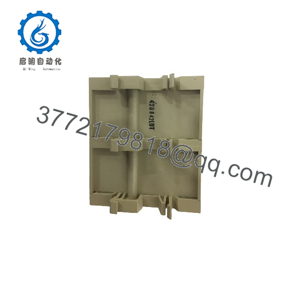
Built with a flame-retardant polyamide housing, the UBE-FL/34 snaps onto standard DIN rails. The angled terminal layout provides easy access for screwdriver insertion and wire entry, making it straightforward to connect solid or stranded conductors with or without wire ferrules.
UBE-FL/34
UBE-FL/34
Engineering Selection Highlights
- 34-Pole Pin-to-Terminal Transition: Converts a 34-pin flat ribbon connector into individual screw clamp terminals for fast field wiring.
- 1:1 Pin Mapping: Direct terminal correlation minimizes wiring mistakes during system layout and panel build.
- DIN Rail Mounting: Snaps onto 35mm DIN rails (TS35) to conserve panel space.
- Accessible Field Connections: Clear terminal labeling and accessible screw terminals simplify wiring maintenance and circuit testing.
- Passive Signal Routing: Operates without internal electronic components, making it compatible with AC or DC low-voltage control signals.
System Compatibility & Integration Requirements
| Item / Dependency | Verified Compatibility or Requirement | Practical Note |
|---|---|---|
| Ribbon Cable Interface | 34-position female ribbon cable connector (HE10 / IDC socket) | Ensure cable socket latching aligns with the header shroud. |
| Mounting Rail | Standard 35mm DIN Rail (TS35) | Verify end stops are installed to prevent module movement along the rail. |
| Field Conductors | Solid or stranded copper wire (with or without ferrules) | Strip wire to recommended length and tighten terminals to rated torque. |
| Control System | PLC / DCS discrete I/O modules utilizing ribbon connector headers | Check system voltage and current limits to ensure they do not exceed module ratings. |
Dimensions, Mounting & Connection Notes
- Installation: Angle the module base onto the upper edge of the 35mm DIN rail and press downward until the locking foot snaps securely into position.
- Ribbon Cable Connection: Align the keying notch on the 34-pin female ribbon connector with the header key on the UBE-FL/34, then press firmly into place.
- Field Wiring: Insert stripped wire ends into the corresponding numbered screw terminal cage and tighten securely. Avoid over-torquing to protect the internal clamping mechanism.
- Clearance: Leave adequate space above the module header to allow ribbon cable insertion, bending radius clearance, and easy cable removal.
FAQ
What is the primary function of the Lütze UBE-FL/34?
The UBE-FL/34 is a passive 34-position interface module that connects a 34-pin flat ribbon cable to individual screw terminals on a DIN rail.
How many positions or pins does the UBE-FL/34 support?
It supports 34 signal positions with a direct 1-to-1 pin mapping between the ribbon cable header and screw terminals.
How is the UBE-FL/34 installed in a control cabinet?
It snaps directly onto a standard 35mm DIN rail (TS35) inside a control panel or cabinet enclosure.
Does the module contain active electronic components?
No. The UBE-FL/34 is a passive breakout module designed purely for physical signal routing and wire termination.
Verification & Troubleshooting Notes
- Signal Continuity Failure: Use a multimeter on continuity mode to check the connection between the ribbon cable pin and the corresponding screw terminal.
- Loose Cable Attachment: Verify that the 34-pin female ribbon connector is fully seated on the header. Confirm that the connector keying tab is aligned correctly with the module header slot.
- Intermittent Channel Contact: Inspect screw terminals for loose wiring or improper wire insulation strip length. Retighten terminal screws to ensure firm clamping on the conductor.
- Short Circuit Between Channels: Check for stray wire strands bridging adjacent terminal blocks, or inspect the ribbon cable for crushed or shorted conductors.