
 WhatsApp: +86 16626708626
 Email:
  Phone: +86 16626708626
Description
Key Technical Specifications
- Manufacturer: MAN B&W / MAN Diesel & Turbo
- Part Number: 3171197-4
- Product Description: HMI panel, HMI module, or engine control indication panel
- Primary Application: MAN B&W marine diesel-engine control and monitoring systems
- Referenced Subsystem: ASD 0150-f
- Known Revisions in Market Listings: Rev. 1.6, Rev. 1.9, and Rev. 9
- Engine Speed Indication Range: 0–120% on Rev. 1.9 listing
- Display Identification: 622-a color display reference reported on Rev. 1.6 listing
- Reported Weight: Approximately 1.29 kg for Rev. 1.6; approximately 1.65 kg for Rev. 9
- Interface Role: Operator status display, alarm indication, diagnostics, and engine-control interaction
- Installation Requirement: Verify rear connector layout, mounting dimensions, revision, and software compatibility against the removed panel
- Condition Note: Surplus-market units may be new without original box, used, or removed from working equipment; inspect the specific unit before purchase
Public surplus listings consistently identify 3171197-4 as a MAN B&W / MAN Diesel & Turbo HMI or engine-control indication panel, but they also show multiple revisions and differing listed weights. Do not treat Rev. 1.6, 1.9, and 9 as automatically interchangeable.
Product Introduction
The MAN B&W 3171197-4 is an HMI panel used in MAN Diesel & Turbo marine-engine automation systems for engine status indication, alarms, diagnostics, and operator control. It is commonly described as an engine-control indication panel or HMI module associated with the ASD 0150-f subsystem.
Buyers normally source this part to restore an existing MAN B&W control installation without changing the engine-control architecture. The part number alone is not enough for a safe replacement: match the installed hardware revision, rear connector arrangement, display condition, and existing system configuration before ordering. Listings have identified Rev. 1.6, Rev. 1.9, and Rev. 9 variants.
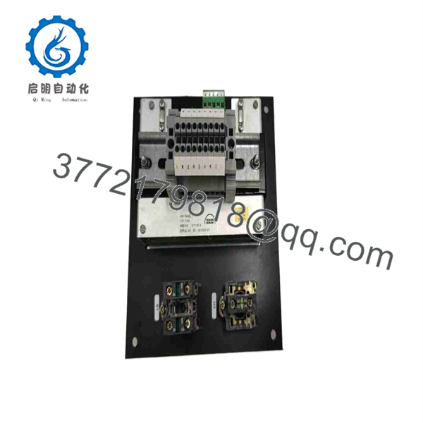
3171197-4
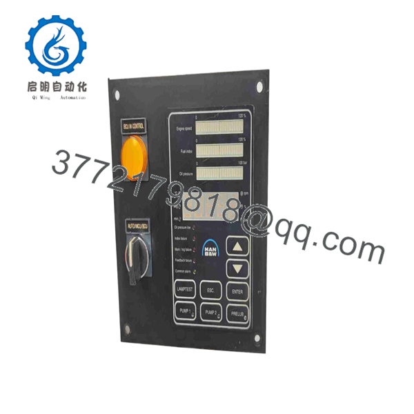
3171197-4
Troubleshooting Quick Reference
| Symptom | Possible Cause | Relevance to This Part | Quick Check Method | Recommendation |
|---|---|---|---|---|
| No display and no panel LEDs | Missing panel supply, blown control-system fuse, loose rear connector, failed HMI | ✅ High | Isolate power correctly, then measure the specified panel supply at the mating connector using the vessel wiring diagram; inspect the fuse and connector retention hardware | Check supply, fuse, and connector engagement before condemning the panel |
| Display backlight is on but no values update | Communication loss between HMI and engine-control system | ✅ High | Check engine-control cabinet diagnostics, network/link indicators, cable continuity, shield termination, and connector pins for corrosion | Verify the communications path and controller status before replacing the HMI |
| Panel shows communication timeout or unavailable data | Incorrect node setup, firmware mismatch, damaged serial/network cable, master-controller fault | ✅ High | Photograph the old unit’s settings, record software/firmware information if available, and compare diagnostic logs before removal | Request the correct revision range; do not assume a higher revision will communicate correctly |
| Touch keys or physical keys do not respond | Failed keypad membrane, damaged front overlay, water ingress, configuration lockout | ✅ High | Check whether the display still updates; inspect the overlay and front seal; test each key only under approved operating conditions | Replace the panel if controls fail while supply and communications are confirmed good |
| Alarms appear on HMI but engine signals are valid elsewhere | HMI configuration issue, failed display logic, intermittent connector contact | ⚠️ Medium | Compare the HMI alarm list with the engine-control system event log and hardwired indicators | Reseat connectors and compare system logs before replacement |
| HMI is completely dead after installation | Wrong revision, incorrect connector mating, damaged pins, ESD event, panel supply incompatibility | ✅ High | Power down, inspect every connector pin, compare pinout and mechanical keying with the removed panel, then verify supply polarity from the OEM drawing | Do not force connectors or repin from memory; return to the original wiring documentation |
| Engine will not start or remains in alarm after HMI replacement | Interlock still active, control-system fault, missing configuration, unrelated engine protection trip | ❌ Usually Low | Review engine-control fault logs, permissive status, emergency-stop loop, safety system, and controller diagnostics | The HMI may only report the fault; troubleshoot the control and protection system first |
Field warning: A dead HMI does not automatically mean the HMI failed. On marine systems, bad connector contact, cabinet power issues, corroded terminals, and controller communication faults cause many apparent panel failures. Measure at the connector, review diagnostic logs, and compare with the old unit before authorizing a replacement.
❗ Firmware revision mismatch: Record the installed panel revision and any available firmware data before pulling the old unit. I have seen technicians replace a visually identical operator panel, then spend days chasing communication faults because the installed control system expected an earlier protocol behavior. Rev. 1.6, Rev. 1.9, and Rev. 9 listings exist for 3171197-4, so revision control matters.
❗ DIP switch, jumper, and address settings: Take clear photos of every accessible switch, jumper, label, and connector before removal. It is the most common avoidable mistake. Mirror the old hardware configuration exactly unless the OEM documentation specifically instructs otherwise.
❗ Terminal and connector compatibility: Do not wire from memory. Similar MAN B&W panel variants can have different rear connections or interface expectations. Check OEM drawings, connector keying, pin assignments, shield grounding, and cable labels before energizing the replacement.
❗ Power budget and supply verification: Confirm the specified supply voltage, polarity, fuse rating, and cabinet ground reference from the vessel documentation. A panel can appear defective when the supply sags under load or a corroded connector drops voltage.
❗ ESD control: Use a grounded wrist strap and handle the unit by its chassis. Static damage can leave a panel looking perfect but dead on first power-up. A 30-second ESD check is cheaper than replacing an obsolete marine HMI.
Keep these checks in mind and you will save yourself 90% of typical rework time. If the fault remains unclear, provide photos of the front and rear labels, connector area, panel status, and engine-control diagnostic logs to technical support.
Frequently Asked Questions
Is MAN B&W 3171197-4 a generic industrial HMI?
No. The 3171197-4 is associated with MAN B&W / MAN Diesel & Turbo marine-engine automation and is commonly listed as an HMI panel or engine-control indication panel. It is intended for a specific installed engine-control architecture, not as a general replacement for a Siemens, Pro-face, Schneider, or Allen-Bradley operator terminal.
Can I replace any 3171197-4 panel with another one?
Not automatically. Verify the revision first. Surplus listings show Rev. 1.6, Rev. 1.9, and Rev. 9 versions, and those revisions may differ in firmware, hardware, display assembly, configuration, or communication behavior. Match the full label information, including the revision and any associated ASD, PD, or MBD numbers, before purchase.
Can I hot-swap the 3171197-4 HMI panel?
Do not assume it is hot-swappable. Unless the applicable MAN B&W vessel documentation explicitly permits live replacement, shut down or isolate the required control supply using the approved maintenance procedure. Removing a powered panel can create connector arcing, corrupt communications, trigger alarms, or damage the interface electronics.
Will I lose programming or settings when I replace the panel?
Possibly. That depends on whether the panel stores local configuration, operating parameters, alarms, calibration information, or firmware-specific settings. Before removal, document the installed revision, capture photos of all labels and switch positions, export or record accessible configuration data, and obtain the OEM-approved startup procedure. Do not assume configuration automatically transfers from the old unit.
What should I send to confirm compatibility before ordering?
Send high-resolution photos of the front label, rear label, connectors, mounting frame, and any revision markings. Include the exact installed part number, revision, vessel or engine-control-system details, fault symptoms, and photos of the display if it still powers up. The critical details are the 3171197-4 revision, rear connector type, ASD reference, and physical panel condition.
Is this part obsolete, and is stock limited?
It should be treated as an obsolete or legacy marine automation item. Current availability generally comes from surplus inventory, used removed equipment, or refurbished stock rather than normal OEM production channels. One listing identifies a new-without-box Rev. 9 unit, while another identifies units removed from a working environment; condition varies by the individual unit.
Why can a New Surplus unit cost less than an OEM factory order?
New Surplus usually means unused inventory acquired outside the current OEM supply chain, often without factory retail packaging or with older date codes. That can reduce cost and lead time, but the seller should verify the exact revision, inspect the display and connectors, provide unit photos, and disclose whether the unit is factory sealed, new without box, refurbished, or used.
What testing should I require before buying a replacement?
Request a documented inspection and test record appropriate to the unit’s condition. At minimum, ask for:
- Label and serial-number photographs for traceability
- Front-display and keypad photographs
- Rear connector and pin-condition photographs
- Power-up video showing boot behavior and status indicators
- Communication test results on a compatible MAN B&W test setup, where available
- A record of the tested revision and firmware information
- ESD-safe packaging confirmation and warranty terms
For a functional test, the supplier should use the correct mating system rather than merely applying power. A meaningful test checks the boot sequence, display behavior, key response, communication handshake, and stable operation under normal supply conditions. Test photos and videos should be available upon request.



