
 WhatsApp: +86 16626708626
 Email:
  Phone: +86 16626708626
Description
Key Technical Specifications
| Parameter | A413125 Specification |
|---|---|
| Manufacturer | Metso Automation / Valmet Automation |
| Part Number | A413125 |
| Module Designation | AIU-8 / AIU 8 |
| Product Type | Analog input module |
| Analog Input Channels | 8 |
| System Application | Metso/Valmet DCS and PLC systems |
| Supply Voltage | 24 VDC |
| Current Consumption | Approximately 30 mA |
| Board Type | Plug-in circuit board |
| Input Signal Type | Analog field signals |
| Module Revision | Revision-specific; Rev. 08, Rev. 22 and other revisions are commercially documented |
| Approximate Listed Weight | 0.12 kg / 0.26 lb |
| Manufacturer Status | Discontinued |
| Typical Procurement | New old stock, used, refurbished, or repair |
The most consistently reported electrical information is 24 VDC supply and approximately 30 mA consumption, together with eight analog input channels. Public sources do not provide enough reliable OEM documentation to establish the exact input voltage/current ranges, resolution, accuracy, or channel isolation for every A413125 revision, so those values should be verified from the installed system documentation rather than inferred.
Multiple physical revisions exist. For example, commercial inventory records explicitly identify A413125 Rev. 08 and A413125 Rev. 22, while other listings show additional revisions. This makes revision verification an important part of replacement selection.
Product Introduction
The Metso Automation A413125 AIU-8 is an eight-channel analog input module used to acquire analog field signals in legacy Metso/Valmet automation systems. It is normally encountered as a circuit-board-level replacement part rather than a modern standalone DIN-rail I/O module.
For maintenance teams, the main replacement issue is not simply matching the part number. Different board revisions are present in the installed base, so the revision, connector arrangement, rack position, field-signal configuration, and host-system compatibility should be checked before installation. A replacement that physically fits but has an incompatible revision or configuration can create an I/O fault or incorrect process values.
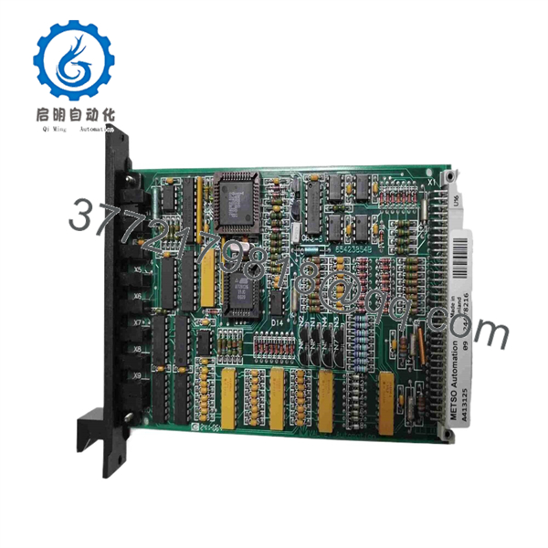
A413125
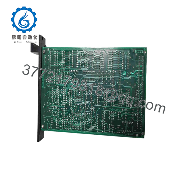
A413125
Installation & Configuration Guide
Stage 1 — Pre-Installation Preparation
Before replacing an :
- Put the affected control loop and process equipment into the approved maintenance condition.
- Apply the site’s LOTO procedure.
- Allow at least 5 minutes for stored electrical energy to discharge, unless the site procedure specifies a longer interval.
- Record the complete part number and revision printed on the existing AIU-8.
- Record the rack and slot position.
- Photograph all field wiring and board connectors.
- Record the eight channel assignments and their configured engineering ranges.
- Back up the relevant DCS/PLC configuration where possible.
- Verify that the replacement is , not another Metso/Valmet analog board.
Because this is legacy equipment, retaining the original board until commissioning is complete is advisable.
Stage 2 — Removing the Existing Module
- Confirm that the affected I/O points have been placed in the approved maintenance state.
- Verify that the module supply is isolated.
- Label field wiring before disconnecting it.
- Release the module’s retaining mechanism.
- Remove the carefully from its backplane/rack connector.
- Inspect the connector and mating backplane for:
- Bent contacts
- Oxidation
- Contamination
- Heat discoloration
- Mechanical damage
- Keep the original module for comparison until the replacement passes functional testing.
Do not assume that an I/O fault originates in the AIU-8 itself. Check the field transmitter, loop power, termination, wiring, and rack/backplane before condemning the module.
Stage 3 — Installing the Replacement
- Wear appropriate ESD protection.
- Compare the replacement board with the original.
- Confirm the part number.
- Confirm the board revision.
- Compare connector locations and board markings.
- Verify the rack/slot assignment.
- Install the module without forcing the connector.
- Secure the module according to the original rack arrangement.
- Reconnect the field wiring channel by channel.
- Verify each wire against the photographs and control-system drawings.
Do not copy jumpers, switches, or configuration links unless the replacement revision actually contains the same hardware and the system documentation confirms their intended settings.
Stage 4 — Power-On & Testing
After installation:
- Verify the 24 VDC supply before energizing.
- Confirm the module powers up normally.
- Check system diagnostics for an AIU or I/O communication fault.
- Verify that all eight channels are recognized.
- Check each transmitter or simulated input independently.
- Confirm the displayed process value against a calibrated source.
- Check engineering-unit scaling.
- Verify high/low alarm behavior where applicable.
- Check channel status and diagnostic information.
- Confirm communication between the I/O module and the host controller.
- Return control loops to automatic operation only after the affected values have been verified.
For acceptance testing, a practical procedure is to simulate known analog values at each channel and compare the DCS/PLC reading against the reference source. The test record should include channel number, applied signal, displayed value, deviation, alarm status, and final disposition.
Frequently Asked Questions (FAQ)
1. What is Metso ?
is the AIU-8, 8-channel analog input unit associated with legacy Metso/Valmet automation systems.
2. How many analog inputs does have?
The AIU-8 provides eight analog input channels. This eight-channel identification is consistently reported across available listings.
3. What power supply does use?
Available technical listings identify 24 VDC operation with approximately 30 mA current consumption. Exact supply tolerances should be confirmed against the system documentation for the particular board revision.
4. Are revisions interchangeable?
Do not assume they are. Multiple revisions are documented, including Rev. 08 and Rev. 22, and additional revisions appear in the installed/aftermarket population. The exact revision should be checked against the existing system before substitution.
5. Is still manufactured?
Available parts databases identify as discontinued by the manufacturer. Current replacement sourcing therefore commonly involves new old stock, used modules, refurbished boards, or repair services.
6. Can I use a generic analog input module instead of ?
Not as a direct hardware replacement. A generic analog input card would require a compatible I/O architecture, electrical interface, controller configuration, signal scaling, and engineering-system integration. is designed for the specific legacy Metso/Valmet system in which it was installed.
7. What should I verify before purchasing an ?
At minimum, verify:
- Exact part number:
- designation
- Board revision
- Rack and slot compatibility
- Field-signal type and range
- Connector condition
- Supply requirements
- Host-system compatibility
- Functional-test availability
- Condition and warranty
For an obsolete analog input module, a seller’s statement that the board “powers on” is not enough. The more useful acceptance test is eight-channel signal simulation and verification against the DCS/PLC values.



