
 WhatsApp: +86 16626708626
 Email:
  Phone: +86 16626708626
Description
Key Technical Specifications
| Parameter | A413240 Specification |
|---|---|
| Manufacturer | Metso Automation / Valmet |
| Part Number | A413240 |
| Board Designation | PIC2 / PIC-2 |
| Product Type | Processor interface card / circuit board assembly |
| System Family | Valmet/Metso legacy automation systems |
| Primary Function | Processor/system interface |
| Installation | Proprietary rack or system card position |
| Hardware Revision | Revision-dependent; Rev. 06 is documented in aftermarket listings |
| Weight | Approximately 0.35 lb / 0.16 kg according to Radwell |
| Field I/O | Not established as a direct analog or digital I/O module |
| Ethernet Interface | Not established from reliable public documentation |
| Modbus/HART | Not established for the exact A413240 |
| Operating Voltage | Not reliably established from primary documentation |
| Operating Temperature | Not reliably established from OEM documentation |
| Manufacturer Status | Discontinued |
Available evidence consistently identifies A413240 as a PIC2 circuit-board/module assembly. Radwell classifies it as a PC board and specifically describes it as “PIC2”; other industrial automation suppliers identify it as a PIC2 Processor Interface Card.
Technical caution: Public documentation for this legacy Metso/Valmet part is limited. I would not treat third-party claims for 230 VAC operation, HART, Modbus RTU, IP20, or specific dimensions as verified A413240 specifications. One supplier publishes those values, but other sources do not corroborate them, and Radwell provides only the board classification and weight.
Product Introduction
The Metso Automation A413240 is a legacy PIC2 processor interface card used in Valmet/Metso automation architectures. Its role is associated with processor/system interfacing rather than serving as a conventional eight-channel analog or digital I/O card. Industrial parts databases list the exact as a PIC2 circuit-board module assembly.
For maintenance and procurement, the important point is that is revision-sensitive legacy hardware. At least one commercial listing identifies a Rev. 06 version, while the base is also listed without a revision. The replacement should therefore be matched against the installed board label, system architecture, connector arrangement, and revision before installation.
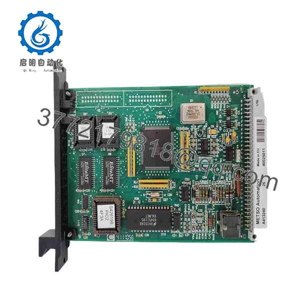
A413240
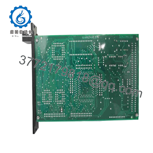
A413240
Installation & Configuration Guide
Stage 1 — Pre-Installation Preparation
Before replacing an :
- Place the affected automation system in its approved maintenance state.
- Follow the site’s LOTO procedure.
- Allow at least 5 minutes for stored electrical energy to discharge, unless the site procedure requires a longer interval.
- Record the complete part number and board revision.
- Record the rack, node, and card-slot position.
- Photograph all connectors and cable routing.
- Record the status of diagnostic LEDs before shutdown.
- Back up the associated system configuration if the engineering system permits it.
- Verify that the replacement is , not another A4132xx or A4130xx board.
Because public OEM documentation is sparse, the original board label and installed system documentation are especially valuable during replacement.
Stage 2 — Removing the Existing Board
- Confirm that the process and control system are in the approved maintenance state.
- Isolate the relevant power according to the plant procedure.
- Label all removable cables before disconnecting them.
- Release the board’s retaining hardware.
- Withdraw the evenly from its card connector.
- Inspect the backplane and card-edge connector.
- Check for:
- Bent contacts
- Oxidation
- Dust or contamination
- Heat discoloration
- Cracked solder joints
- Mechanical damage
- Retain the original board for comparison until commissioning is complete.
Do not automatically condemn the board when the system reports a communication fault. Backplane connections, power supplies, adjacent processor boards, and system configuration can produce similar symptoms.
Stage 3 — Installing the Replacement
- Use appropriate ESD protection.
- Compare the replacement PCB against the removed .
- Confirm the exact part number.
- Confirm the board revision.
- Verify connector positions and board markings.
- Confirm the correct rack/card position.
- Insert the card without forcing the backplane connector.
- Secure the board using the original retention method.
- Reconnect cables exactly as documented.
- Check that no connector has been displaced or installed in the wrong position.
Do not reproduce jumper, switch, or configuration settings unless the replacement board has the same hardware and the system documentation confirms their function.
Stage 4 — Power-On & Testing
After installation:
- Verify the power supply before energizing the rack.
- Power the system using the approved startup sequence.
- Check the status indicators.
- Confirm that the processor/interface subsystem recognizes the board.
- Check system diagnostics for or communication errors.
- Verify communication with the associated processor/controller.
- Check downstream I/O or subsystem status.
- Review system event logs.
- Confirm normal data exchange before returning the process to automatic operation.
For an obsolete processor-interface board, functional acceptance should go beyond a basic power-on test. A useful test record should document board identification, revision, rack position, power-on status, diagnostics, processor communication, and system-level data exchange.
Frequently Asked Questions (FAQ)
1. What is Metso ?
is a Metso Automation/Valmet circuit board module, commonly described as a Processor Interface Card.
2. Is an analog input or digital output module?
No reliable source identifies as a conventional analog-input or digital-output module. The strongest available listings classify it as a PC board / processor interface card.
3. What does mean in ?
is the board designation used in commercial and industrial parts documentation for . The available descriptions characterize it as a processor/interface board within Valmet/Metso PLC automation architecture.
4. Is still manufactured?
Radwell explicitly lists as discontinued by the manufacturer. Current procurement therefore generally involves existing inventory, new old stock, refurbished boards, or repair services.
5. Are different revisions interchangeable?
They should not be assumed interchangeable. Commercial sources document revision-specific units, including Ver. 06. Compare the revision on the installed board with the replacement and verify compatibility in the applicable Valmet/Metso system documentation.
6. Can A413240A replace ?
Do not make that substitution based only on the similar part number. Some aftermarket listings show A413240A associated with the family, but the available public evidence does not establish universal interchangeability. Confirm the exact hardware revision, connectors, system generation, and software/configuration requirements first.
7. What should be checked before purchasing a replacement?
For a legacy , verify:
- Exact part number
- designation
- Hardware revision
- Board markings and serial number
- Physical connector arrangement
- Rack/card position
- System generation
- Configuration/firmware compatibility where applicable
- Functional-test availability
- Condition and warranty
A seller’s “powers on” statement is not sufficient for a processor-interface board. The useful acceptance test is system-level: power-up → board recognition → diagnostics → processor communication → subsystem data exchange.



