
 WhatsApp: +86 16626708626
 Email:
  Phone: +86 16626708626
Description
Key Technical Specifications
| Parameter | Specification |
|---|---|
| Model | D201129 |
| Module Type | DO8P Digital Output Unit |
| Manufacturer | Metso Automation |
| I/O Series | ACN I/O Units, M80 Series |
| Number of Channels | 8 |
| Output Type | PNP digital output |
| Switching Element | Normally open mechanical relay |
| Output Voltage | 17–30 VDC |
| Output Current | < 200 mA |
| Short-Circuit Current | < 300 mA |
| Minimum Allowed Load Impedance | 160 Ω |
| Maximum Inductive Load | < 3 W |
| Relay Life | 5 × 10⁶ operations at 32 VDC, 0.25 A load |
| Safe-State Transition Time | Configurable, 1 s–4 h |
| Channel Safe State | No change / 0 / 1 |
| Housing Size | 95 × 24 × 95 mm (H × W × D) |
| Weight | 90 g |
| Compatible Mounting Bases | MB2 and MB8 |
| Field Connection | 16-pin flat-cable interface |
The published technical documentation specifies eight channels, 17–30 VDC output, less than 200 mA output current, less than 300 mA short-circuit current, a 160 Ω minimum load impedance, and an inductive-load limit below 3 W. The same documentation specifies a 95 × 24 × 95 mm housing and 90 g weight.
The MB2 and MB8 mounting bases use a 16-pin flat-cable interface. For the D201129, the documented channel arrangement assigns output and common connections across channels 0 through 7; cross-connection boards such as CXS, CXW, and CXR use a corresponding mapped arrangement.
Product Introduction
The Metso D201129 DO8P is an eight-channel PNP digital output unit for the Metso ACN I/O, M80 Series. It switches field loads such as signal lamps and solenoid valves and can control motors or valves through supplementary relays. Each output uses a normally open mechanical relay with current-limited field supply.
For legacy Metso DNA installations, the D201129 provides a compact interface between control logic and discrete field devices. Its configurable safe-state behavior is useful where loss of the I/O communication path must produce a defined output response.
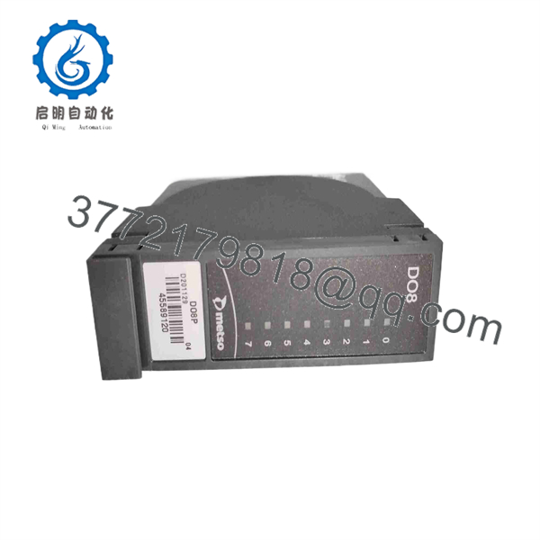
D201129
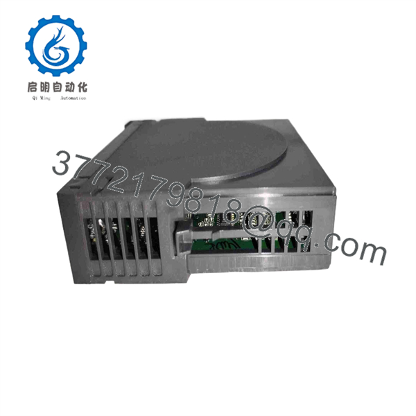
D201129
Installation & Configuration Guide
Stage 1 — Pre-Installation Preparation
Estimated time: 20–30 minutes
- Apply LOTO (Lockout/Tagout) to the affected I/O cabinet and field power sources.
- Wait at least 5 minutes before handling the module.
- Wear an ESD wrist strap when handling the D201129.
- Prepare a PH1 screwdriver, calibrated multimeter, wire labels, and a camera or smartphone.
- Record the existing D201129 part number and revision information.
- Photograph the module, mounting base, flat-cable connection, terminal arrangement, and status LEDs.
- Back up the applicable Metso DNA configuration before removing the module.
- Confirm that the replacement is specifically marked .
- Verify that the installed mounting base is compatible with the documented MB2 or MB8 interface.
⚠️ Do not substitute another D2011xx module based on the part-number family alone. D201126, , and D201134 perform different I/O functions.
Stage 2 — Removing the Existing Module
Estimated time: 15–20 minutes
- Verify that the cabinet and relevant field circuits are isolated.
- Measure the field supply with a multimeter before disconnecting the wiring.
- Label all field conductors and identify each output channel.
- Photograph the original channel assignments.
- Disconnect the field wiring or applicable connection unit.
- Disconnect the flat-cable interface from the mounting base.
- Release the module’s mechanical retaining mechanism.
- Remove the without placing mechanical stress on the mounting base.
- Inspect the MB2/MB8 base, connectors, and cable for contamination, damaged contacts, or loose connections.
⚠️ If the original module failed while driving a solenoid, valve, or other inductive load, investigate the field load before installing the replacement.
Stage 3 — Installing the New
Estimated time: 20–30 minutes
- Compare the replacement with the removed unit, including model, revision, connector arrangement, and physical dimensions.
- Confirm the eight-channel DO8P identity before insertion.
- Inspect the connector contacts and mounting base.
- Install the into the designated position.
- Secure the module mechanically.
- Reconnect the flat cable according to the applicable Metso connection documentation.
- Reconnect field wiring according to the original channel schedule.
- Confirm that the connected load remains within the documented <200 mA output-current limit.
- Check that the load impedance is at least 160 Ω where the specified output interface requires that minimum.
- For inductive loads, verify that the application remains within the documented <3 W inductive-load limit.
- Verify that any motor or valve requiring more output power uses the appropriate supplementary relay arrangement.
⚠️ The documentation describes the output as a normally open mechanical relay. Do not treat it as a generic solid-state transistor output module when checking load compatibility.
Stage 4 — Power-On & Testing
Estimated time: 30–60 minutes
- Restore the applicable field and I/O power according to site procedures.
- Check the status indicators.
- Verify that the Metso DNA system recognizes the I/O unit without a module fault.
- Confirm each configured channel against the engineering database.
- Perform a channel-by-channel output test using an approved test load or the actual field device.
- Verify that each output reaches the intended ON/OFF state.
- Confirm the correct channel mapping from the control system to the field device.
- Test the configured fail-safe response where permitted by the plant’s commissioning procedure.
- Check the configurable safe-state behavior: No change, 0, or 1.
- Verify the configured transition time, which the documentation specifies as adjustable from 1 s to 4 h.
- Monitor the module and connected loads for abnormal heating or repeated output faults.
- Record the test results before returning the I/O cabinet to normal operation.
Frequently Asked Questions (FAQ)
1. What is the Metso ?
The is the DO8P eight-channel digital output unit used in Metso ACN I/O, M80 Series systems. It provides PNP-type field outputs for devices such as signal lamps and solenoid valves.
2. How many outputs does provide?
The provides 8 digital output channels, identified as channels 0 through 7 in the documented connection arrangement.
3. What voltage does the output?
The documented output voltage range is 17–30 VDC. The specified output current is less than 200 mA, with a short-circuit current below 300 mA.
4. Is a relay output module?
Yes. The technical documentation describes each channel as a normally open mechanical relay output. The relay arrangement can control signal lights and solenoid valves directly within the specified electrical limits; motors and larger valves can be controlled through supplementary relays.
5. What mounting base does use?
The documentation describes connections through MB2 and MB8 mounting bases using a 16-pin flat-cable interface. Verify the exact cabinet connection arrangement before replacement because cross-connection boards can change the field wiring path.
6. Can I replace with another D2011xx module?
No—not without checking the system documentation. D2011xx part numbers can represent different I/O functions. For example, D201126 is documented as a different digital-input unit, while is the DO8P digital-output unit. Treat the complete part number and module designation as mandatory identification fields.
7. What should I verify before purchasing a replacement ?
Request a clear nameplate photograph and verify , module revision, physical condition, connector arrangement, and compatibility with the existing MB2/MB8 installation. For a critical DCS application, also confirm the eight-channel output configuration and the field-load requirements before accepting a substitute.



