
 WhatsApp: +86 16626708626
 Email:
  Phone: +86 16626708626
Description
Key Technical Specifications
| Parameter | Value |
|---|---|
| Model | D201466 |
| Type Designation | DII8P24 |
| Brand | Metso Automation |
| Product Family | ACN I/O M120 |
| I/O Type | Digital Input |
| Number of Channels | 8 |
| Nominal Field Voltage | 24 VDC |
| Field Voltage Range | 18–32 VDC |
| Input Impedance | 3.5 kΩ |
| Channel Current Limit | 40 mA |
| Maximum Leakage Current | 1.5 mA |
| Input Filtering | τ = 0.5 ms |
| Pulse Counting Frequency | <400 Hz |
| Shortest Parameterizable Pulse | 1 ms |
| Pulse Hold Time | 0–1,250 ms |
| Measuring Interval | 1.0 ms |
| Installation | TS35 rail mounting base |
| Address Selection | Rotary switch S1 |
| Dimensions | 130 × 24 × 95 mm |
| Weight | Approximately 110 g |
The published M120 technical documentation specifies D201466 as the DII8P24 variant and distinguishes it from the 48 VDC DII8P48/D201467. The same documentation gives the electrical and timing values listed above.
Product Introduction
Metso Automation D201466, designated DII8P24, is an 8-channel digital input unit for the ACN I/O M120 platform. It accepts 24 VDC field signals and supports configurable pulse-counting operation, making it suitable for discrete status monitoring and pulse-based field applications.
The key replacement issue is matching the field-voltage version. D201466 is the 18–32 VDC DII8P24 variant; D201467 is the corresponding 40–58 VDC DII8P48 version. Do not substitute them solely because their channel counts are identical.
Installation & Configuration Guide
Stage 1: Pre-Installation Preparation
Estimated time: 5–10 minutes
⚠️ Safety First: Notify operations, place the controlled process in a safe state, and apply the site’s lockout/tagout procedure before removing the I/O unit.
Tools Required:
- ESD wrist strap
- Small Phillips screwdriver if required by the mounting assembly
- Digital multimeter
- Wire labels
- Smartphone or camera for configuration records
Data Backup:
- Record the existing I/O unit’s exact designation: D201466 / DII8P24.
- Photograph the existing wiring before disconnection.
- Record the mounting-base and cable arrangement.
- Photograph the address setting on rotary switch S1.
- Confirm that the field supply is appropriate for the 24 VDC version.
- Keep the removed unit available for comparison until commissioning is complete.
⚠️ Do not assume that a visually similar Metso I/O unit is electrically interchangeable. D201466 is specifically the DII8P24 version, while D201467 is the 48 VDC DII8P48 variant.
Stage 2: Removing the Old Module
Estimated time: 5 minutes
- Confirm that the I/O group is de-energized according to the site’s maintenance procedure.
- Identify the position in the M120 mounting assembly.
- Label each field connection before disconnecting it.
- Disconnect the field wiring without pulling on the conductors.
- Release the module from its mounting base.
- Pull the unit straight out rather than twisting it against the connector.
- Inspect the connector and mounting base for contamination, bent contacts, or mechanical damage.
The is used with M120 mounting-base arrangements and associated cross-connection cabling. Metso training documentation specifically lists among the I/O units supported by the S446448 cable hood set.
⚠️ Keep the old module until the replacement has passed functional testing. Its switch position and wiring arrangement are useful references if the commissioning results are unexpected.
Stage 3: Installing the New Module
Estimated time: 5–10 minutes
- Verify the replacement marking: / DII8P24.
- Put on the grounded ESD wrist strap before handling the PCB or module.
- Compare the replacement module with the removed unit.
- Set the address rotary switch S1 to match the documented original configuration.
- Confirm that the mounting base and connector arrangement correspond to the M120 installation.
- Insert the module carefully into the mounting position.
- Ensure that the module is fully seated.
- Reconnect the field wiring according to the photographs and wiring documentation.
- Check that each conductor is mechanically secure.
Self-Checklist:
- / confirmed
- S1 address confirmed
- 24 VDC field supply confirmed
- Wiring matches original documentation
- Module fully seated
- No loose conductors
- ESD precautions followed
Stage 4: Power-On & Testing
Estimated time: 10–15 minutes
- Before energizing, use a multimeter to check the field supply and verify that no obvious short circuit exists.
- Energize the I/O group according to the plant commissioning procedure.
- Check the control system for I/O communication or module diagnostics.
- Verify that the is recognized at the expected I/O address.
- Apply a known 24 VDC input signal to each channel in a controlled test.
- Confirm that each corresponding input changes state correctly.
- If pulse-counting functionality is used, test it with a known pulse source within the module’s specified operating range.
- Verify all eight channels before returning the process to automatic operation.
⚠️ Do not test as though it were the 48 VDC D201467. The documented field-voltage ranges are different: operates with 18–32 VDC field voltage, while D201467 is specified for 40–58 VDC.
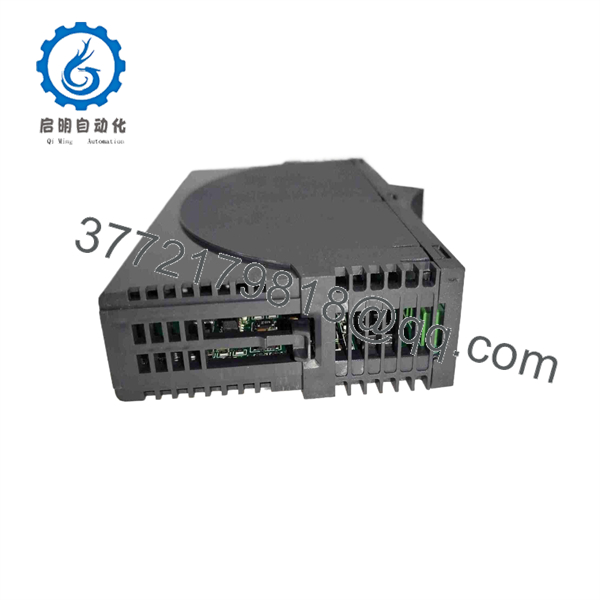
D201466
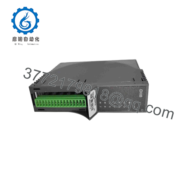
D201466
Frequently Asked Questions (FAQ)
Can be used as a 48 VDC digital input module?
No. is the version, specified for an 18–32 VDC field supply. The 48 VDC version is D201467 / DII8P48. The two should not be treated as interchangeable simply because both provide eight digital input channels.
How many digital inputs does the provide?
provides 8 digital input channels. The Metso documentation identifies it as the unit.
What is the input voltage range of ?
The documented field-voltage range is 18–32 VDC, with 24 VDC as the nominal application voltage. The input impedance is specified as 3.5 kΩ.
Can perform pulse counting?
Yes. The technical documentation specifies a pulse-counting mode below 400 Hz, with a parameterizable shortest pulse length of 1 ms and pulse hold time from 0 to 1,250 ms.
Is obsolete?
The available documentation identifies as an ACN I/O component, but the sources reviewed here do not establish its current OEM lifecycle status. For a replacement purchase, verify current OEM support and the exact revision required by the installed system.
What should I verify before ordering a replacement ?
At minimum, verify , the eight-channel digital-input configuration, 24 VDC field application, mounting-base compatibility, and the required hardware revision. If your existing unit is marked , do not order without confirming the field-voltage requirement.
Will replacing erase the PLC/DCS configuration?
The I/O unit itself is not the same type of device as a standalone PLC CPU containing the complete control program. However, the replacement must match the configured I/O address and system hardware configuration. Record the existing S1 setting and verify the I/O configuration after installation. The documentation identifies S1 as the address-selection switch for I/O units mounted on the base.



