
 WhatsApp: +86 16626708626
 Email:
  Phone: +86 16626708626
Description
Key Technical Specifications
| Parameter | Value |
|---|---|
| Model | D201483 |
| Type Designation | FII4 / FII4V |
| Brand | Metso Automation / Valmet |
| Product Family | ACN I/O M120 |
| I/O Type | Frequency & Pulse Input |
| Number of Channels | 4 |
| Nominal Signal Voltage | 24 V |
| Primary Function | Frequency and pulse measurement |
| Mounting System | M120 I/O mounting system |
| Cross-Connection Support | IXR8 / IXR16 |
| Cable Hood Set | S446448 |
| Direct Terminal Connection Cable Family | S446497–S446503 |
The M120 cross-connection documentation explicitly lists FII4 D201483 alongside DII8P24, DII8P48, AII8-series, AOI4-series, TII4-series, and TCI8 modules. It also specifies S446448 as the cable hood set used with D201483.
Important: The sources reviewed confirm the FII4 designation, 24 V application, four-channel configuration, and M120 integration. They do not provide enough reliable information to state detailed electrical limits such as exact frequency range, input threshold, accuracy, or isolation rating. Those values should be verified against the applicable OEM revision before installation.
Product Introduction
Metso Automation D201483 FII4 is a four-channel frequency and pulse input module for the ACN I/O M120 platform. It is intended to acquire frequency or pulse signals in process-control applications. Procurement documentation identifies the variant as FII4V, 24 V, while Metso M120 documentation lists D201483 among the compatible I/O units.
For replacement work, the important checks are the exact D201483/FII4 identification, 24 V signal application, four-channel configuration, and mounting/cross-connection arrangement. Do not substitute another frequency-input module based only on channel count or physical appearance.
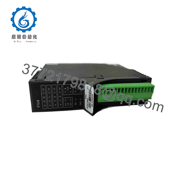
D201483
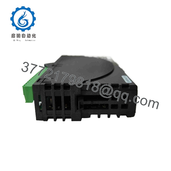
D201483
Installation & Configuration Guide
Stage 1: Pre-Installation Preparation
Estimated time: 5–10 minutes
⚠️ Safety First: Place the controlled process in a safe state and follow the plant’s lockout/tagout procedure before removing the module.
Tools Required:
- ESD wrist strap
- Digital multimeter
- Appropriate screwdriver
- Wire labels
- Smartphone or camera for documentation
Data Backup:
- Record the existing module marking and hardware revision.
- Photograph the installation before removal.
- Record the wiring for all four channels.
- Photograph the module position and associated mounting base.
- Document the I/O address or channel assignment in the control-system configuration.
- Confirm that the replacement is / FII4, not another I/O type.
The documentation identifies as an unit and shows it connected through the cross-connection architecture.
Stage 2: Removing the Old Module
Estimated time: 5 minutes
- Confirm that the relevant I/O section has been safely de-energized.
- Identify the position in the assembly.
- Label all field connections before disconnecting them.
- Disconnect the wiring carefully; do not pull on the conductors.
- Release the module from its mounting arrangement.
- Pull the module straight out.
- Inspect the connector and mounting base for contamination, bent contacts, or mechanical damage.
⚠️ Keep the removed available during commissioning. Its wiring and physical configuration provide a useful reference if the replacement does not behave as expected.
Stage 3: Installing the New Module
Estimated time: 5–10 minutes
- Verify the replacement marking: / .
- Ground yourself with the ESD strap before handling the module.
- Compare the replacement module with the removed unit.
- Verify the mounting base and connector arrangement.
- Install the module without forcing the connector.
- Confirm that the module is fully seated.
- Reconnect the field wiring according to the recorded wiring arrangement.
- Check each connection mechanically.
- Confirm that the frequency/pulse channels correspond to the correct control-system points.
Self-Checklist:
- / confirmed
- 24 V application confirmed
- Four channel assignments verified
- mounting arrangement confirmed
- Wiring matches documentation
- Module fully seated
- ESD precautions followed
The documentation specifically associates with the S446448 cable hood set and the S446513–S446519 cable family for IXR16 cross-connection boards.
Stage 4: Power-On & Testing
Estimated time: 10–15 minutes
- Check the applicable supply voltage with a multimeter before energizing.
- Power the I/O section according to the plant commissioning procedure.
- Verify that the control system recognizes the expected I/O unit.
- Check module diagnostics.
- Apply a known frequency or pulse signal to channel 1.
- Verify that the corresponding control-system value changes correctly.
- Repeat the test for channels 2–4.
- If the application uses frequency measurement, compare the displayed value with a calibrated signal source.
- Check for abnormal diagnostics or unstable readings.
- Return the process to normal operation only after all configured channels have passed testing.
⚠️ Do not assume the detailed frequency limits from another Metso frequency-input module. The sources reviewed confirm as /FII4V but do not provide sufficient evidence for a reliable exact frequency-range specification.
Frequently Asked Questions (FAQ)
What is Metso ?
is the frequency and pulse input unit used in the ACN I/O system. Documentation lists it alongside other I/O modules and identifies it as compatible with the cross-connection architecture.
Is a digital input module?
Not in the ordinary discrete-input sense. is designated , a frequency and pulse input module. A conventional 24 V digital input module in the same family is D201466 / DII8P24.
How many channels does have?
is a four-channel frequency/pulse input unit. A procurement specification identifies it as “Frequency & Pulse I/P unit, 24V.”
Is a 24 V module?
Available procurement documentation identifies FII4V as a 24 V frequency/pulse input unit. Confirm the exact electrical requirements against the OEM documentation for your hardware revision before applying field signals.
Can be connected directly to terminal blocks?
Yes, the Metso cross-connection documentation lists among the I/O units supported by the S446497–S446503 cable family for direct connection to terminal blocks. It also lists for connection through IXR8 and IXR16 cross-connection boards.
What should I verify before purchasing a replacement?
Verify the part number, designation, 24 V application, four-channel configuration, compatibility, mounting arrangement, and hardware revision. If your existing module has a different suffix or revision marking, provide that complete marking to the supplier rather than ordering from the base number alone.
Is obsolete?
The sources reviewed establish that is an older ACN I/O component, but they do not provide a current OEM lifecycle statement sufficient to declare its present obsolescence status. For an existing plant replacement, confirm current availability and revision compatibility with the supplier before committing to a substitute.



