
 WhatsApp: +86 16626708626
 Email:
  Phone: +86 16626708626
Description
Key Technical Specifications
| Parameter | Value |
|---|---|
| Manufacturer | Metso Automation |
| Product Family | maxPAC I/O |
| Model Marking | IOP32 — exact suffix requires verification |
| System Architecture | Metso maxPAC / maxDNA I/O |
| System Supply | 24 VDC ±4.0 VDC for maxPAC I/O system |
| I/O Bus | 8-bit parallel asynchronous I/O bus |
| I/O Bus Transfer | Up to 10 µs transfers |
| Operating Temperature | 0 to 60°C |
| Relative Humidity | 0 to 90%, noncondensing |
| DPU Interface | maxPAC DPU architecture |
| Installation | maxPAC I/O chassis/backplane |
| Compatibility Note | Confirm the complete part number before replacement |
The published documentation identifies IOP320 as an 8-channel, 4–20 mA common-output module. It requires eight I/O bus addresses and uses a 24 V loop supply through the backplane. If your physical label actually reads IOP320, rather than IOP32, the specifications below should be based on IOP320.
For IOP320 specifically:
- Output Channels: 8
- Output Signal: 4–20 mA
- Resolution: 12 bit
- Accuracy: ±0.1% of reading, ±0.05% of full scale at 25°C
- Load Impedance: 0–800 Ω
- Input Power: 175 mA from the 24 V system supply
- Calibration: Self-calibration at power-up when the calibration jumper is configured
- Bus Addressing: Eight addresses; base address must fall on an 8-address boundary
- Watchdog: Approximately 0.7-second I/O-bus communication timeout
- Field Connection: 16-pin connector, with two connections per analog-output channel
Product Introduction
Metso Automation IOP32 is identified as a legacy maxPAC I/O designation, but the published Metso documentation does not establish IOP32 as a complete standalone model number. The documented related model IOP320 is an 8-channel 4–20 mA analog-output module used with the maxPAC/maxDNA distributed control architecture.
Before purchasing or installing an IOP32-labeled unit, verify the complete part number, PCB marking, connector arrangement, and existing DPU configuration. Do not substitute IOP320, IOP321, or another IOP3xx module solely because the front-panel designation appears similar.
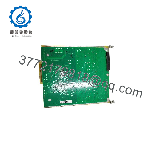
IOP320
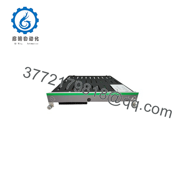
IOP320
Installation & Configuration Guide
Stage 1: Pre-Installation Preparation — 5–10 minutes
⚠️ Safety First: Follow the site’s approved maintenance procedure. Confirm the process is in a safe state and obtain the required maintenance authorization. Although Metso documentation states that maxPAC I/O modules can be inserted and withdrawn with 24 VDC and field power applied, do not assume that every installation permits live work.
Tools Required:
- ESD wrist strap
- PH1 screwdriver
- Digital multimeter
- Wire labels
- Smartphone or camera
- Appropriate terminal/connector tools
Data Backup:
- Record the complete module identification from the front label and PCB.
- Photograph the module before removal.
- Photograph all DIP switches and jumpers.
- Photograph the terminal/connector wiring.
- Record the existing I/O bus address.
- Confirm the associated DPU and maxPAC configuration.
- Retain the old module until commissioning is complete.
⚠️ Do not order a replacement based solely on “IOP32.” The Metso documentation uses distinct part numbers such as and IOP321.
Stage 2: Removing the Old Module — 5 minutes
- Put the process and control system into the approved maintenance state.
- Identify the exact module position and corresponding I/O channels.
- Label field wiring before disconnecting anything.
- Remove the front retaining hardware as applicable.
- Disconnect the field connector without pulling on the conductors.
- Release the module’s mechanical retaining mechanism.
- Pull the module straight out of the maxPAC chassis.
- Inspect the backplane connector for contamination, bent contacts, or mechanical damage.
⚠️ Keep the old module. Its switch and jumper configuration may be required to reproduce the original installation.
Stage 3: Installing the Replacement — 5–10 minutes
- Put on the grounded ESD wrist strap.
- Verify the replacement’s complete model number and hardware revision.
- Compare the connector, board layout, switch arrangement, and mounting dimensions with the original.
- Clone the original configuration exactly.
- For an installation, verify the module’s eight-address allocation and base address.
- Verify any output-state/watchdog jumper configuration against the original installation.
- Insert the module squarely into the chassis.
- Ensure the module seats fully in the backplane connector.
- Reconnect the field connector.
- Secure the module and wiring according to the original installation.
Self-Checklist:
- Complete model number verified
- Hardware revision checked
- Address switches match
- Jumpers match
- Connector orientation verified
- Field wiring labeled correctly
- Module fully seated
- Retaining hardware secured
Stage 4: Power-On & Testing — 10–15 minutes
- Perform a visual inspection before energizing the system.
- Check the relevant 24 VDC supply with a multimeter.
- Power the I/O rack according to the approved startup procedure.
- Observe the module’s Active LED.
- Verify that the DPU recognizes the module.
- Confirm the configured I/O address.
- Check diagnostic status.
- For an , verify each configured 4–20 mA output channel using an appropriate loop measurement method.
- Test the engineering-unit scaling in the DCS.
- Confirm the final output at the field device under controlled conditions.
For , the Active LED indicates system power and communication with the DPU. The module also provides diagnostic codes for conditions such as RAM, CPU, checksum, interrupt, FPGA, and channel calibration faults.
⚠️ If communication fails: stop and verify the exact module type, bus address, jumper configuration, DPU compatibility, and physical seating before changing the DCS configuration.
Frequently Asked Questions (FAQ)
Q1. Is Metso the same product as ?
Do not assume that it is. The Metso maxPAC Hardware Reference Guide specifically documents as an 8-channel 4–20 mA analog-output module, while the documentation reviewed does not establish “” as a complete model designation. Verify the label before purchasing.
Q2. What does the do?
converts DPU commands into eight 4–20 mA analog outputs. The module uses the maxPAC I/O bus and provides loop power through the backplane. The documented output load range is 0–800 Ω.
Q3. Can the maxPAC I/O module be hot-swapped?
Metso’s maxPAC documentation states that its I/O modules may be inserted and withdrawn with 24 VDC and field power applied.
That does not mean every plant should perform a live replacement. Follow the site’s electrical safety procedures and process-control maintenance rules. For a critical control output, a controlled shutdown or approved maintenance bypass may still be required.
Q4. Will pulling the I/O module erase the DCS configuration?
Removing the physical I/O module does not normally erase the configuration stored in the DCS/DPU. The bigger risk is installing a module with the wrong address, wrong hardware type, or incorrect jumper configuration. Back up and document the existing configuration before replacement.
Q5. What should I verify before ordering an ?
Send the supplier a clear photograph of the module label and connector area. Verify the complete model number, part number, hardware revision, I/O function, and address configuration. This is particularly important with legacy Metso/maxPAC equipment because IOP3xx modules perform different functions.
Q6. Why can a surplus Metso I/O module cost less than an OEM replacement?
Legacy automation components can enter the secondary market as new surplus, discontinued inventory, or professionally tested used stock. Price alone does not establish condition. Ask for the exact condition classification, photographs of the actual unit, serial/part-number information, and a functional test report where available.
Q7. Is obsolete?
The maxPAC documentation is legacy documentation, and current market listings identify several Metso/Valmet maxPAC I/O modules as discontinued by the manufacturer.
For an specifically, however, I would not label the unit obsolete until its complete part number is confirmed. If you meant , that is the documented 8-channel 4–20 mA maxPAC analog-output module.



