
 WhatsApp: +86 16626708626
 Email:
  Phone: +86 16626708626
Description
Key Technical Specifications
| Parameter | Specification |
|---|---|
| Manufacturer | Micro Innovation AG |
| Model | GF1-10TVD-000 |
| Product family | Micro Panel GF1 |
| Display size | 10.4 in. / 264 mm |
| Display technology | TFT LCD color |
| Resolution | VGA, 640 × 480 |
| Supply voltage | 24 VDC |
| Supply type | Electrically isolated |
| Operator input | Touch zone interface |
| Project engineering | GALILEO |
| Project storage | External PC Card |
| Expansion | 2 slots for communication modules/system expansion |
| Mounting | Panel/enclosure mounting |
| Front protection | IP65 when installed according to the specified mounting procedure |
The Micro Innovation GF1 documentation distinguishes the GF1-10TVD from the GF1-10TVB and AC-powered GF1-10TVA. The TVD version uses a 10.4-inch TFT color display, 640 × 480 VGA resolution, and isolated 24 VDC power.
The -000 suffix should be preserved when ordering. Do not substitute a GF1-10TVD-100, -101, or -102 solely because the base GF1-10TVD designation matches. These are separately identified variants in the replacement market.
Product Introduction
The Micro Innovation GF1-10TVD-000 is a 10.4-inch Micro Panel GF1 operator interface designed for visualization and operator control in medium- to high-complexity automation systems. It uses a TFT color LCD with 640 × 480 VGA resolution and an electrically isolated 24 VDC supply.
The GF1 platform stores visualization projects on an external PC Card and uses GALILEO engineering software for project creation. Two expansion slots allow communication modules or system expansions to be installed, making the exact communication configuration dependent on the installed hardware.
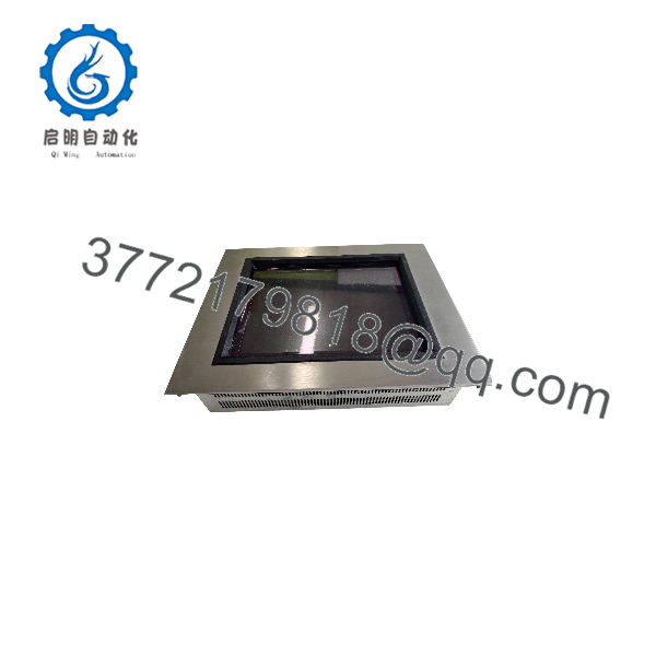
GF1-10TVD-000
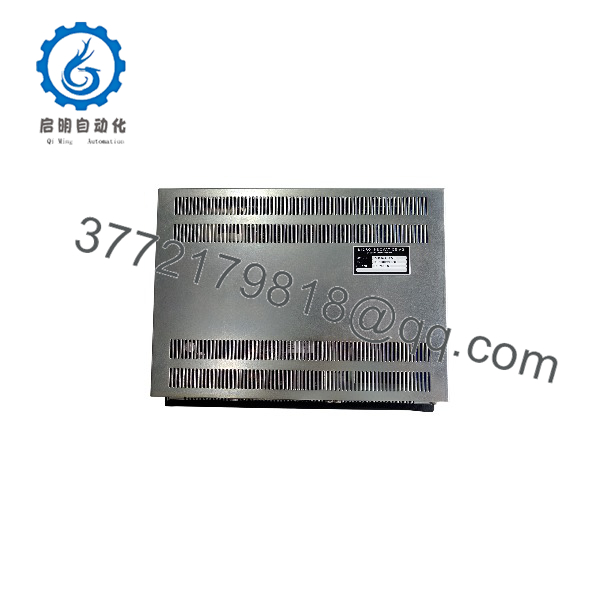
GF1-10TVD-000
Installation & Configuration Guide
Step 1 — Verify the Existing HMI
Before removing the installed panel:
- Record the complete part number, including the
-000suffix. - Photograph the front and rear of the existing unit.
- Record installed communication modules and expansion cards.
- Record the existing PC Card/project configuration.
- Confirm that the replacement is GF1-10TVD-000, not another variant.
Warning: , GF1-10TVB, and GF1-10TVA have different power-supply configurations. The TVD version is the 24 VDC isolated version.
Step 2 — Back Up the HMI Project
- Stop the machine using the plant’s normal shutdown procedure.
- Preserve the existing HMI project and PC Card where possible.
- Record communication-module part numbers.
- Document PLC address, baud rate, node address, and other communication settings if applicable.
- Keep the original HMI available until the replacement has passed commissioning.
The GF1 platform requires the appropriate project data to be loaded before operation; the documentation identifies GALILEO as the design software and the external PC Card as the project-data medium.
Step 3 — Remove the Existing Panel
- Isolate the 24 VDC supply.
- Verify that the panel is de-energized.
- Apply ESD protection when handling the electronics.
- Disconnect the DC power connector.
- Disconnect installed communication modules and field connections.
- Release the panel mounting hardware.
- Remove the HMI without stressing the rear connectors.
Step 4 — Install the Replacement
- Inspect the replacement -000 for physical damage.
- Compare the rear connectors and expansion configuration with the original.
- Transfer compatible communication hardware only after confirming the module identification.
- Install the panel in the original enclosure cutout.
- Install the sealing components correctly.
- Tighten the mounting hardware evenly.
- Reconnect the isolated 24 VDC supply.
- Reconnect communication wiring according to the original installation records.
The GF1 installation documentation specifies mounting arrangements for enclosure/cabinet installation and states that the mounting method provides a sealed installation to IP65 when the specified procedure is followed.
Step 5 — Commission the HMI
- Energize the 24 VDC supply.
- Confirm normal startup.
- Insert or restore the correct project PC Card.
- Verify that the intended visualization project loads.
- Test touchscreen operation across the display.
- Confirm communication with the PLC or automation controller.
- Test alarms, status indications, operator commands, and data displays.
- Run the machine through a controlled operating cycle.
- Record the installed HMI model, revision, and project version.
Common Replacement Problems
HMI powers up but the application does not load
Check the PC Card and project data first. The GF1 requires appropriate project data before it can operate as the intended visualization unit.
The HMI powers up but cannot communicate with the PLC
Check the installed communication module and its configuration. The GF1 platform uses communication modules to connect the operator panel to the automation system, so the base HMI model alone does not establish the complete communication configuration.
A -100 is available but the original is -000
Do not treat the two as automatically interchangeable. Confirm the complete model, hardware revision, communication configuration, and project compatibility before substitution.
FAQ
What is the Micro Innovation -000?
It is a Micro Panel GF1 industrial operator interface with a 10.4-inch TFT color display, VGA 640 × 480 resolution, touch operation, and isolated 24 VDC power.
What is the difference between and GF1-10TVB?
The documented distinction is primarily the power supply configuration. uses electrically isolated 24 VDC, while GF1-10TVB uses non-isolated 24 VDC. Both use the 10.4-inch TFT color/VGA display configuration.
What software is used to program the GF1?
The Micro Panel GF1 documentation identifies GALILEO as the design software for creating the device’s visualization project.
Where is the HMI project stored?
The GF1 platform uses an external PC Card for project data. The documentation states that project data can be transferred to the memory card through a download or directly from a PC.
Does the -000 include communication modules?
The base GF1 platform provides two slots for communication modules or system expansions. The actual communication capability therefore depends on the modules installed in the particular unit.
discontinued?
The GF1 family is a legacy product line. Specialist automation suppliers currently list GF1 variants as discontinued, wh units remain available through the industrial surplus market.
What should I verify before purchasing a replacement?
Verify the complete model number, display type, power configuration, installed communication modules, project-storage method, physical mounting arrangement, and project compatibility. For a legacy HMI, a photograph of the original nameplate and rear panel is particularly useful for confirming the correct variant.



